Spatially extendible annular tensioning integrated antenna mechanism

A technology of tensegrity and antenna, which is applied in the field of satellite wireless communication, can solve the problems of large overall quality and low reliability of deployment, and achieve the effect of simple deployment control, mature processing technology, and guaranteed shape and surface accuracy

Active Publication Date: 2015-11-18
HARBIN INST OF TECH
View PDF7 Cites 18 Cited by
  • Summary
  • Abstract
  • Description
  • Claims
  • Application Information

AI Technical Summary

Problems solved by technology

[0004] In order to solve the problem that the existing expandable loop antenna needs a large number of mechanical connections during the process of unfolding and foldi

Method used


Image

  • Spatially extendible annular tensioning integrated antenna mechanism
  • Spatially extendible annular tensioning integrated antenna mechanism
  • Spatially extendible annular tensioning integrated antenna mechanism

Examples


specific Embodiment approach 1

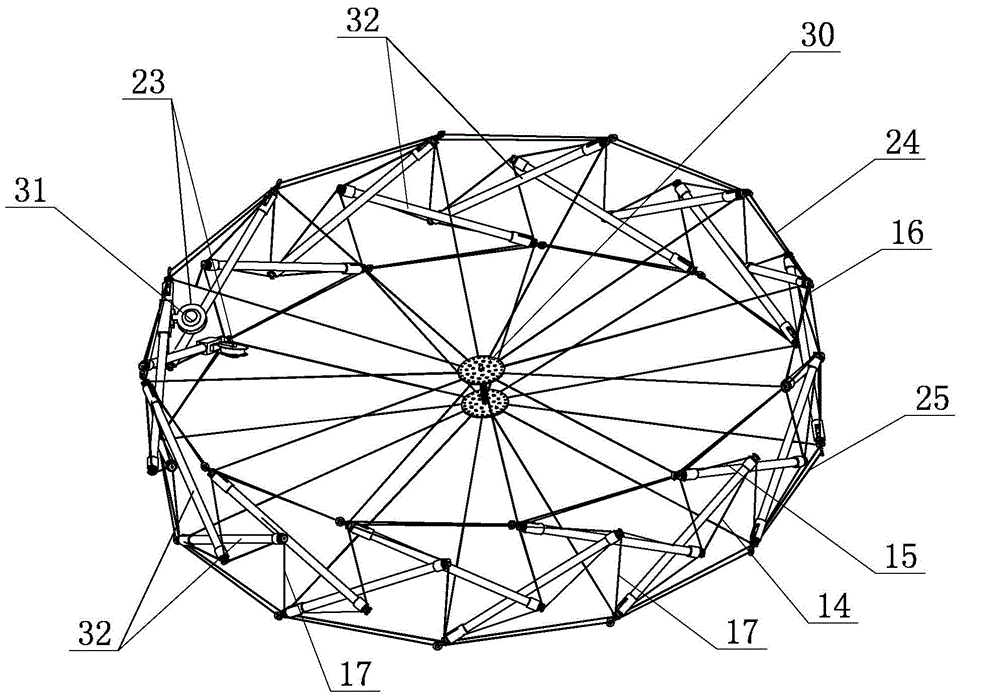
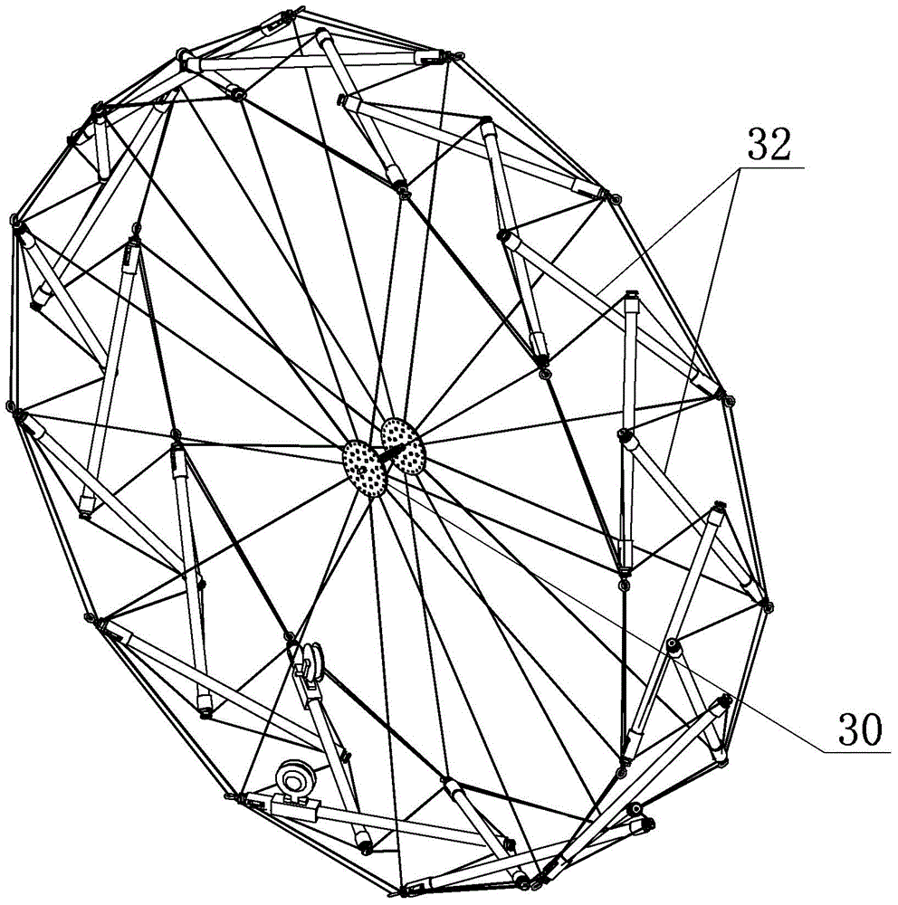
[0020] Specific implementation mode one: as Figure 1-9 As shown, the space-expandable annular tensioned integral antenna mechanism of this embodiment includes an intermediate tensioning device 30, a slow release device 31, multiple tensioned integral rods 32 and multiple tensioning cables;

[0021] The middle tensioning device 30 comprises a tension spring 20 and two thin sheets 19, the two thin sheets 19 are arranged parallel up and down, and the tension spring 20 is vertically arranged between the two thin sheets 19;

[0022] The slow release device 31 includes two slow release pulleys 23 with damping;

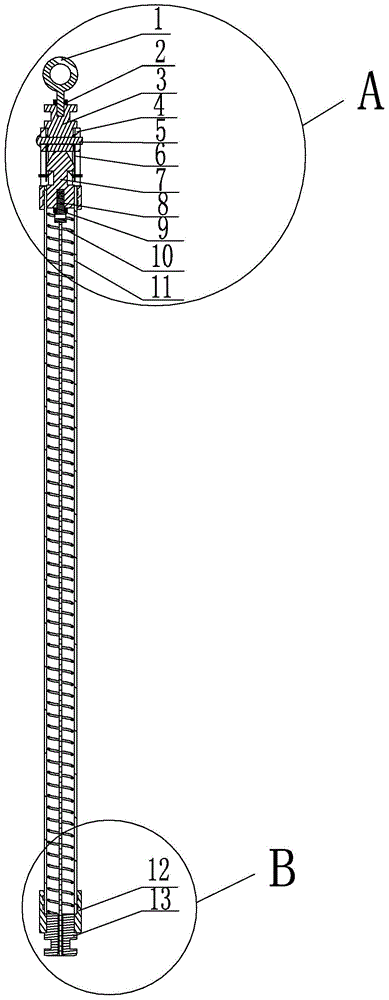
[0023] Each tensioned integral rod 32 includes an end suspension ring 1, a main end firmware 3, a main end connecting pipe 4, a guide slider 7, a slider screw 8, a drive spring 10, a carbon fiber tube 11, a secondary end connector 12, a secondary The end piece 13 and two locking leaf springs 6; the main end piece 3 is firmly connected to one end of the main end connecting ...

specific Embodiment approach 2

[0027] Specific implementation mode two: as image 3 with Figure 4 As shown, the two-shaped openings 4-1 described in this embodiment are symmetrically arranged on the main-end connecting pipe 4, and the two locking leaf springs 6 are symmetrically arranged on the two-shaped openings 4-1 of the main-end connecting pipe 4. place. Such a design has the advantages of high locking efficiency, symmetrical locking force, stable and reliable locking. Other components and connections are the same as those in the first embodiment.

specific Embodiment approach 3

[0028] Specific implementation mode three: as image 3 with Figure 4 As shown, the tensioned integral rod 32 in this embodiment further includes an end nut 2 , and the end nut 2 is threadedly connected to the end suspension ring 1 . Such a design can realize disassembly and adjustment of the structure, and provide access for the installation of internal parts. Other compositions and connections are the same as those in Embodiment 1 or 2.


PUM


Abstract

The invention provides a spatially extendible annular tensioning integrated antenna mechanism, relates to antenna mechanisms, and solves the problems that a present extendible annular antenna needs lots of mechanical connection in the folding and unfolding process and further causes high total weight and low unfolding reliability. A main-end fixation member is fixedly connected with one end of a main-end connecting tube via a pin, the other end of the main-end connecting tube is fixedly connected with one end of a carbon fiber tube, two bar-shaped openings are formed in the sidewall of the main-end connecting tube along the length direction, two locking flat springs are arranged correspondingly at the positions of the bar-shaped openings, a drive spring is placed in the carbon fiber tube, an annular groove is formed in the middle portion of a guiding slide block circumferentially, when the antenna mechanism is unfolded, the lower portion of the locking flat springs are clamped in the annular groove of the guiding slide block, the lower end of the guiding slide block is connected with a slide block screw, the guiding slide block is placed at the upper end of the driving spring, an auxiliary-end fixation piece is fixedly connected with the other end of the carbon fiber tube via an auxiliary-end connecting piece, and the amount of tensioning integrated rods is an even number. The antenna mechanism is used in the field of wireless communication.

Description

technical field [0001] The invention relates to a foldable antenna mechanism, in particular to a space-expandable ring tension integral antenna mechanism, which belongs to the field of satellite wireless communication. Background technique [0002] With the development of human space industry, large antennas play an important role in various tasks, such as earth observation, deep space exploration, radio astronomy and other fields, and play a leading role in long-distance communication. Therefore, the large-scale antenna For the research hotspot of deployable antenna. In order to meet the capacity requirements of the transmitter, the large-aperture antenna must be made into a deployable form. Such a deployable antenna has high requirements on the mechanism, thermal environment, and radio frequency, and also needs to meet the deployment reliability, so it is a challenging multi-faceted design problem. Although the large-scale deployable loop antennas currently used can real...

Claims


Application Information

Patent Timeline
IPC IPC(8): H01Q1/08H01Q15/14
Inventor 郭宏伟刘荣强李长洲邓宗全李冰岩
Owner HARBIN INST OF TECH
Why Eureka
Try Eureka