Calibration device, imaging device, calibration method, and method for manufacturing imaging device
一种校正装置、摄像装置的技术,应用在放映装置、洗印装置、图像通信等方向,达到减小不使用区域、消除振动的效果
- Summary
- Abstract
- Description
- Claims
- Application Information
AI Technical Summary
Problems solved by technology
Method used
Image
Examples
Embodiment approach 1
[0029] Regarding other embodiments of the present invention, based on Figure 1 ~ Figure 4 described as follows.
[0030]
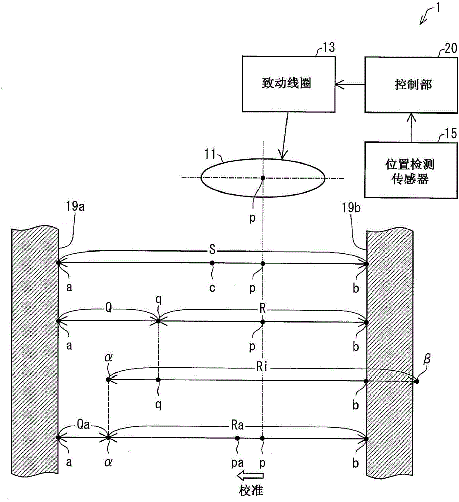
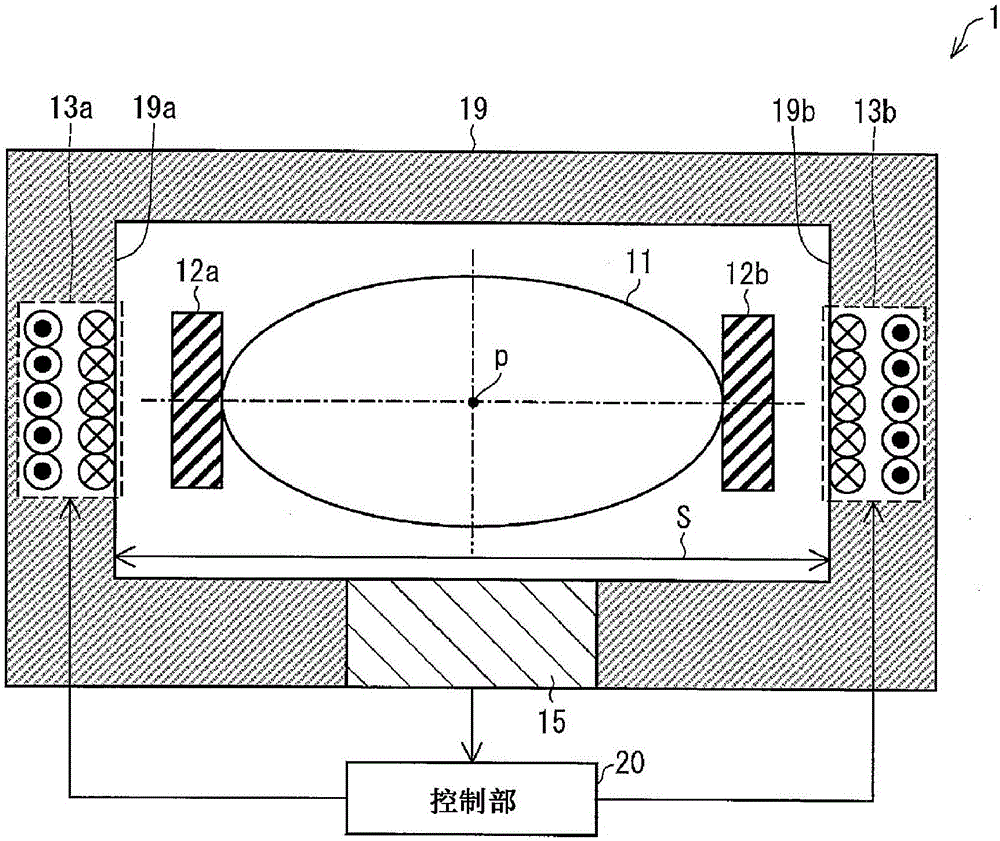
[0031] figure 1 It is a figure which shows the calibration apparatus 1 and calibration method of this embodiment. Such as figure 1As shown, the correction device 1 includes a correction lens (optical element) 11 , an actuator coil (drive device) 13 , a position detection sensor (position detection device) 15 , and a control unit (intermediate position correction unit) 20 . With such a configuration, the correction lens 11 is moved by allowing a current within the rated current to flow in the actuation coil 13 to eliminate vibration caused by hand shake, and the unused area can be reduced compared to before correction. Each component included in the calibration device 1 will be described in detail below.
[0032] (correction lens 11)
[0033] The correction lens 11 is incorporated into an imaging device or the like together with an actuator coil 1...
Embodiment approach 2
[0067] based on Figure 5 Other embodiments of the present invention will be described below. In addition, for the sake of convenience of description, members having the same functions as those described in the above-mentioned embodiments are given the same reference numerals and their descriptions are omitted.
[0068]
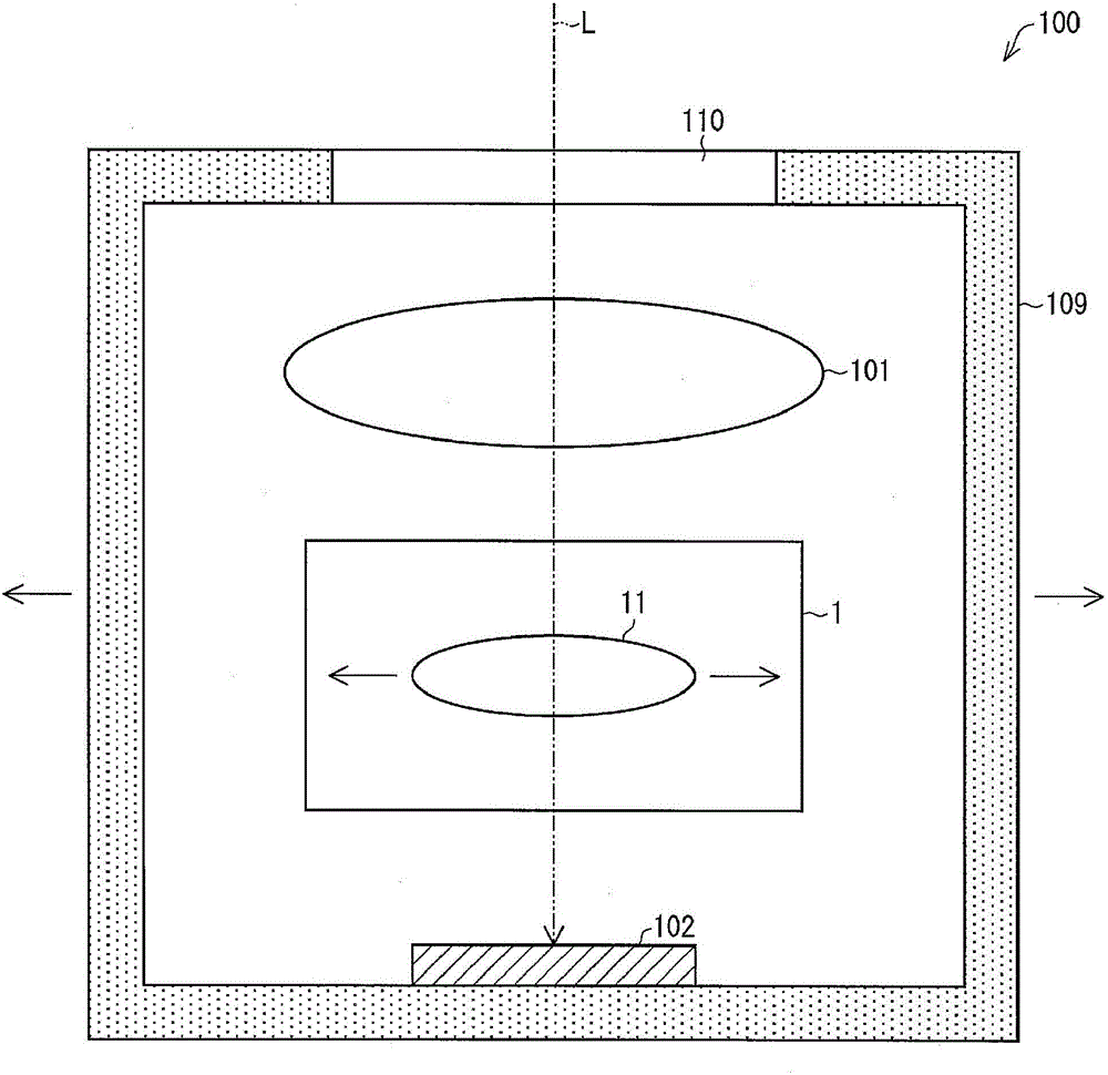
[0069] Figure 5 It is a cross-sectional view showing the configuration of the imaging device 100A and the calibration device 1A of the present embodiment. Here, the imaging device 100A is equipped with image 3 The camera device 100 shown has the same structure, but as Figure 5 As shown, it differs from the imaging device 100 in further including an interactive control unit (calibration instruction information generation unit) 50 and an interface 130 for intermediating between the interactive control unit 50 and the calibration device 1A. In addition, the calibration device 1A is equipped with figure 1 The correction device 1 shown in etc. has the s...
Embodiment approach 3
[0074] The following is based on Figure 6 Other embodiments of the present invention will be described. In addition, for convenience of description, members having the same functions as those described in the above-mentioned embodiments are denoted by the same reference numerals, and descriptions thereof are omitted.
[0075]
[0076] Figure 6 It is a cross-sectional view showing the configuration of the imaging device 100B and the calibration device 1B of the present embodiment. Here, the imaging device 100B is equipped with image 3 The imaging device 100 shown has the same configuration, and the calibration device 1B has the same configuration as image 3 The calibration device 1 shown has the same structure, but as Figure 6 As shown, the correction device 1B is different in that it moves the image sensor (optical element) 102 instead of the correction lens.
[0077] That is, the calibration device 1B includes: an image sensor 102 housed in the space between the f...
PUM
 Abstract
Description
Claims
Application Information
 - R&D
- Intellectual Property
- Life Sciences
- Materials
- Tech Scout
- Unparalleled Data Quality
- Higher Quality Content
- 60% Fewer Hallucinations
Browse by: Latest US Patents, China's latest patents, Technical Efficacy Thesaurus, Application Domain, Technology Topic, Popular Technical Reports.
© 2025 PatSnap. All rights reserved.Legal|Privacy policy|Modern Slavery Act Transparency Statement|Sitemap|About US| Contact US: help@patsnap.com


