The method of edge pressing with electronically controlled permanent magnet technology

An electronically controlled permanent magnet and blank holder technology, which is applied in metal processing equipment, forming tools, manufacturing tools, etc., can solve the problems of complex composition and structure of the control system, inability to provide blank holder force control, high manufacturing cost and energy consumption, etc. To achieve the effects of compact structure, long-term stability, and improved quality and precision

Inactive Publication Date: 2017-04-26
YANSHAN UNIV
View PDF7 Cites 2 Cited by
  • Summary
  • Abstract
  • Description
  • Claims
  • Application Information

AI Technical Summary

Problems solved by technology

The rigid blank holder method indirectly controls the blank holder force by limiting the displacement, and cannot provide accurate blank holder force control
For elastic blank holders applied by rubber or springs, the blank holder force increases with the increase of the drawing stroke. This method generally does not meet the requirements of the deep drawing process; elastic blank holders with liquid or gas as the force transmission medium The method can provide constant blank-holding force or variable blank-holding force, but the composition and structure of the control system are generally very complicated, the manufacturing cost and energy consumption are very high, and there are few applications in actual production at present.

Method used


Image

  • The method of edge pressing with electronically controlled permanent magnet technology
  • The method of edge pressing with electronically controlled permanent magnet technology
  • The method of edge pressing with electronically controlled permanent magnet technology

Examples


Embodiment Construction

[0020] Below in conjunction with accompanying drawing and specific embodiment the present invention is described in further detail:

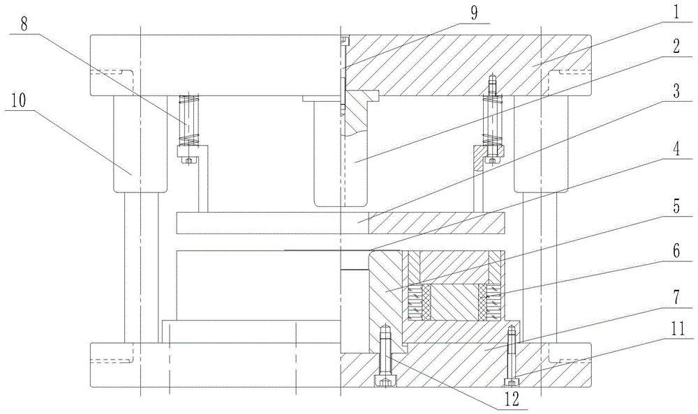
[0021] A kind of method of the present invention adopts electronically controlled permanent magnet technology to carry out blank-holding, the deep-drawing forming mold that this method uses is as figure 1 As shown, it includes an upper die base 1, a punch 2, a binder plate 3, a die 5, an electric permanent magnet chuck 6, a lower die base 7, a discharge screw 8, a set screw 9 and a press slide 10 ; The drawing and forming die assembly using electronically controlled permanent magnet technology for blank blanking adopts a formal structure, the punch 2 is on the top, the die 5 is on the bottom, and the punch 2 is installed and fixed on the upper die base 1 through the set screw 9 The press slider 10 is two left and right symmetrically installed on the upper mold base 1, the upper mold base 1 and the press slider 10 are in interference fit, and the...


PUM


Abstract

The invention discloses a drawing forming die with blank pressing conducted by adopting an electronic control permanent magnet technique and a blank pressing method of the drawing forming die. The assembly of the drawing forming die with blank pressing conducted by adopting the electronic control permanent magnet technique is of a forward erection structure; the drawing forming die comprises an upper die base, a male die, a pressing plate, a female die, an electronic control permanent magnet sucking disc, a lower die base, a stripper bolt, a stopper screw and press sliding blocks; the male die is installed on the upper die base; the two press sliding blocks are installed on the upper die base symmetrically in the horizontal direction; the pressing plate is installed on the upper die base in a symmetric mode in the horizontal direction; the electronic control permanent magnet sucking disc is installed on the lower die base; the female die is located in a circular through hole in the center of the electronic control permanent magnet sucking disc; the female die is installed on the lower die base; the upper surface of the female die and the upper surface of the electronic control permanent magnet sucking disc are located on the same horizontal plane; the lower die base is provided with two vertical sliding channels which are symmetric in the horizontal direction; the two press sliding blocks are arranged on the two vertical sliding channels in a sleeving mode respectively and can slide along the vertical sliding channels freely in the vertical direction; the press sliding blocks are in clearance fit with the vertical sliding channels correspondingly; a through hole is formed in the center of the pressing plate, and the male die can penetrate the through hole and enter a female die cavity.

Description

technical field [0001] The invention relates to the field of plate forming, in particular to a method for blank-holding by using an electronically controlled permanent magnet technology. The magnetic attraction of an electronically controlled permanent magnet chuck generates a blank-holding force to prevent wrinkling of the plate and complete the deep-drawing forming process of the plate. Background technique [0002] Deep drawing is one of the basic deformation methods of sheet metal stamping forming, and wrinkling instability is one of the main failure modes in the forming process. The method of using blank holder is an important means to suppress wrinkling instability and control the forming process. [0003] Existing hemming methods mainly include rigid hemming and elastic hemming. The rigid blank holder method is to indirectly control the blank holder force by means of limited displacement, which cannot provide accurate control of the blank holder force. For elastic b...

Claims


Application Information

Patent Timeline
Patent Type & Authority Patents(China)
IPC IPC(8): B21D37/10B21D22/22B21D24/04B21D24/10
Inventor 秦泗吉王国佐马亚飞孔晓华邓超
Owner YANSHAN UNIV
Why Eureka
Try Eureka