
A steel pipe beveling machine

A technology of beveling machine and steel pipe, which is applied to the details of milling machine equipment, metal processing equipment, milling machine equipment, etc., can solve the problems of small application range and unreasonable design of pipe fixtures, etc., and achieve the effect of simple structure and reasonable design

Active Publication Date: 2018-01-05
浙江德威不锈钢管业股份有限公司
View PDF8 Cites 2 Cited by
  • Summary
  • Abstract
  • Description
  • Claims
  • Application Information

AI Technical Summary

Problems solved by technology

This kind of automatic pipe fitting beveling machine has an unreasonable design of the pipe fitting fixture, which can only be matched with the corresponding pipe fittings, and the scope of application is small

Method used


Image

  • A steel pipe beveling machine
  • A steel pipe beveling machine
  • A steel pipe beveling machine

Examples


Embodiment 1

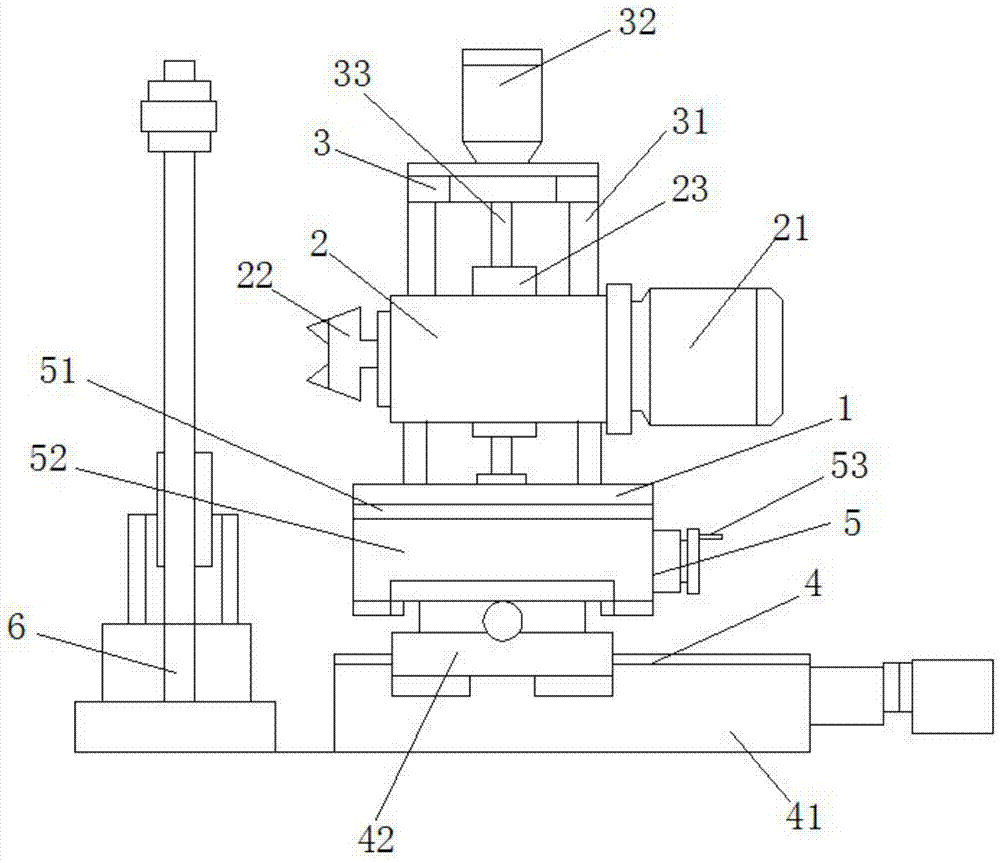
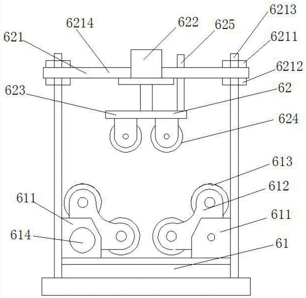
[0019] see Figure 1 to Figure 4 , The steel pipe beveling machine of this embodiment includes a support frame 1 , a milling device 2 , a lifting device 3 , a moving device 4 , a rotating device 5 and a fixing device 6 .

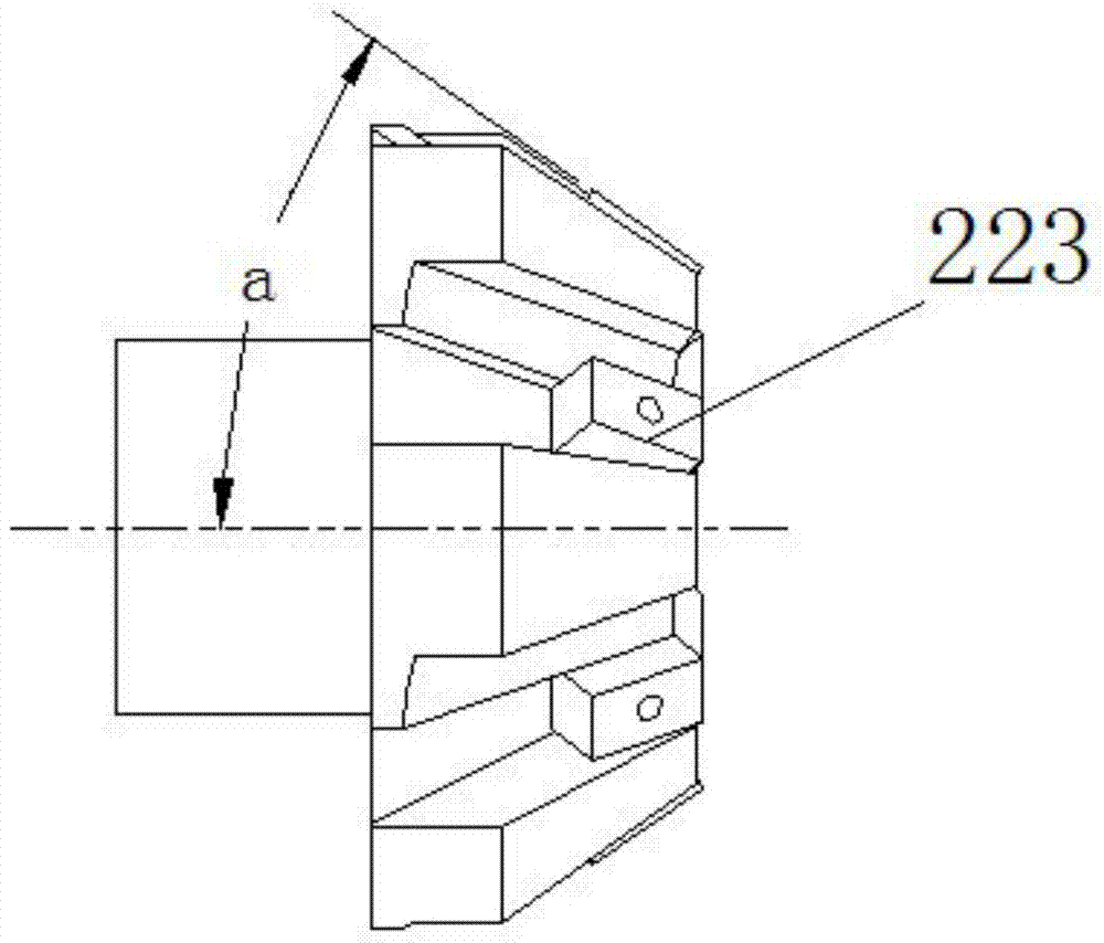
[0020] Milling device 2 among the present embodiment comprises drive motor 21 and machine head 22, and drive motor 21 drives machine head 22 to rotate, and machine head 22 comprises mounting base 221 and cutter 222, and the mounting base 221 is provided with several along its surface circular arrangement. Mounting groove 223, cutter 222 is installed in the mounting groove 223, cutter 222 has cutting edge 223, the included angle between the cutting edge 223 of cutter 222 and the axis of mounting base 221 is an acute angle, therefore, during use, needn't milling device whole Offset so that it forms a certain angle with the steel pipe, and a chip removal groove 224 is correspondingly provided on the mounting seat 221 adjacent to the mounting groove 223 . The d...


PUM


Abstract

The invention provides a facing machine for a steel tube. A common lathe cannot clamp the large-caliber steel tube. The facing machine comprises a supporting frame, a milling device, a lifting device, a moving device and a rotating device. The milling device comprises a driving motor and a machine head, and is provided with a sliding block. The lifting device comprises a guiding rod, a lifting motor and a screw rod, wherein the guiding rod penetrates the milling device, the screw rod is connected with the lifting motor, and the screw rod is in threaded fit with the sliding block of the milling device. The rotating device is fixed to the supporting frame. The moving device is connected with the rotating device. The machine head comprises an installation seat and cutters. The installation seat is provided with a plurality of installation grooves annularly arranged along the surface of the installation seat, the cutters are installed in the installation grooves, and chip grooves are formed in the installation seat. The steel tube facing machine is simple in structure, reasonable in design, wide in application range, high in working efficiency and convenient to operate.

Description

technical field [0001] The invention relates to a steel pipe beveling machine, which is used for beveling the end face of the steel pipe. Background technique [0002] The pipe bevel refers to a slope formed by processing and grinding the interface when the pipe and the pipe are welded. There are 45-degree and 30-degree grooves, and there are also V-shaped, U-shaped, and I-shaped grooves in form. Specific groove forms can be selected according to different pipe wall thicknesses. Before the steel pipe is welded, it is usually necessary to perform groove treatment, that is, to process a groove on its end face. In the prior art, small-diameter steel pipes are generally turned by lathes, that is, after the steel pipe is fixed, the end face is chamfered. . However, when running into a steel pipe with a large diameter, ordinary lathes cannot clamp it, so it cannot be applied. [0003] The application publication date is September 25, 2013, and the Chinese patent application pub...

Claims


Application Information

Patent Timeline
Patent Type & Authority Patents(China)
IPC IPC(8): B23C3/12
CPCB23C3/122
Inventor 沈根荣胡开磊莫培明张林荣马同杰
Owner 浙江德威不锈钢管业股份有限公司
Learn More