Fixture structure

A fixture and workpiece technology, applied in the field of fixture structure, can solve the problems of increasing tool processing cost, wasting calibration time, and low processing efficiency, and achieve the effects of saving calibration time, reducing processing cost, and high processing efficiency

Active Publication Date: 2015-11-25
SUZHOU MITAC PRECISION TECH
View PDF5 Cites 1 Cited by
  • Summary
  • Abstract
  • Description
  • Claims
  • Application Information

AI Technical Summary

Problems solved by technology

[0006] Therefore, the object of the present invention is to provide a fixture structure to solve the following problems in existing mechanical processing of step-shaped workpieces with rectangular grooves and semicircular grooves: waste of on-site calibration time and low processing efficiency; The wire cutting process is used during processing, and the processing cost is high; special tools are required to increase the processing cost of the tool

Method used


Image

  • Fixture structure
  • Fixture structure
  • Fixture structure

Examples


Embodiment Construction

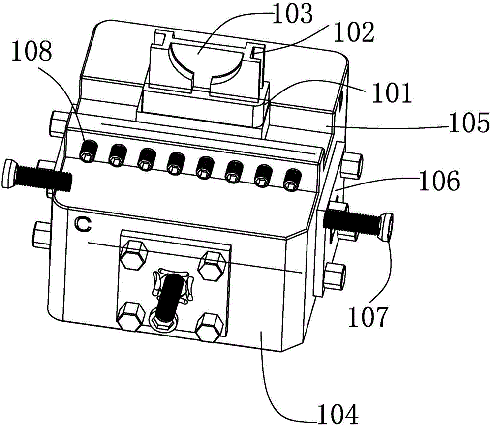
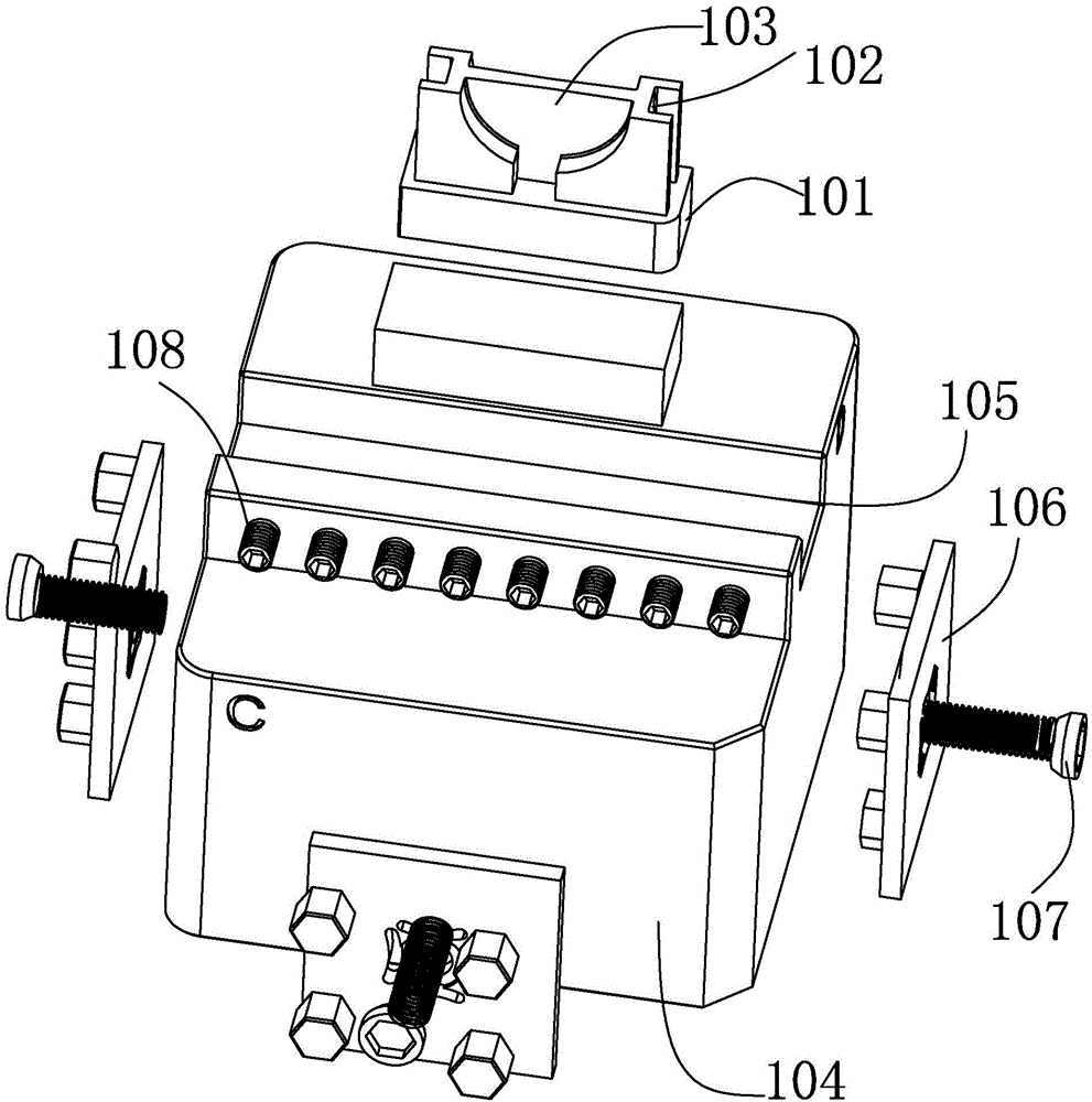
[0018] Please refer to figure 2 , image 3 , figure 2 It is a schematic diagram of the first processing state of a preferred embodiment of the centering fixture structure of the present invention, image 3 shown as figure 2 Schematic diagram of the breakdown structure.

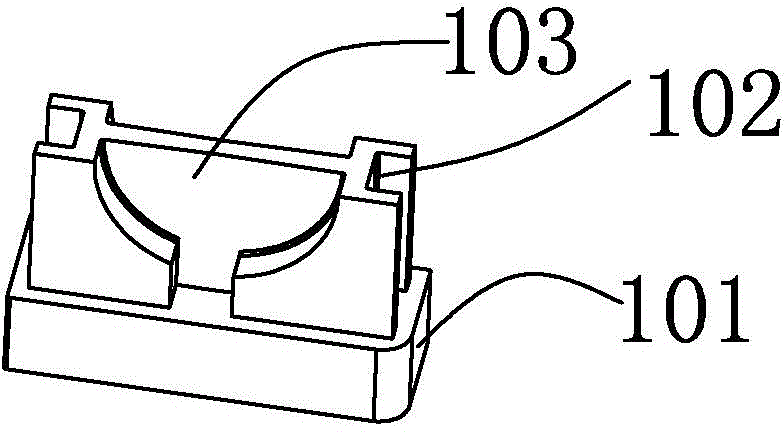
[0019] The fixture structure provided by the present invention clamps a stepped workpiece 101 with a rectangular groove 102 and a semicircular groove 103 ( Figure 2-5 In order to facilitate the understanding of the processed parts of the workpiece 101, the workpiece 101 is shown as the processed workpiece 101), and the fixture structure is arranged on a CNC milling machine, and the structure includes:

[0020] The base 104 has a top surface, a bottom surface, a left side, a right side, a front surface and a back surface, the top surface is provided with a workpiece groove 105, and the workpiece 101 is clamped in the workpiece groove 105;

[0021] Spacers 106, which are respectively arranged on the bot...


PUM


Abstract

The invention discloses a fixture structure, which is used for clamping a stepped workpiece having a rectangular groove or a semicircular groove. The fixture structure is arranged on a CNC milling machine, and comprises a base, washers and set screws, wherein the base is provided with a top surface, a bottom surface, a left side surface, a right side surface, a front surface and a back surface, the top surface is provided with a workpiece groove, and a workpiece is clamped in the workpiece groove; the washers are respectively arranged at the bottom surface, the left side surface, the right side surface, the front surface and the back surface; certain ends of the set screws are fixed onto the washers, and the other ends of the set screws are free ends. By adoption of the structure, the stepped workpiece having the rectangular groove or the semicircular groove can be obtained through the CNC milling machine. Hence, through the steps, the meter calibration time in the field can be saved, and the processing efficiency is high; a wire cutting processing is not needed, so that the processing cost is low; a special chamfering tool is not needed, so the processing cost brought by the tool is reduced.

Description

【Technical field】 [0001] The invention relates to the field of machining, in particular to a fixture structure used in machining. 【Background technique】 [0002] see figure 1 , figure 1 It is a schematic diagram of a workpiece structure. As shown in the figure, the workpiece 101 can be processed by a rectangular block, the workpiece 101 is basically in the shape of a step, one of the opposite sides of the workpiece 101 has a rectangular groove 102, and the other opposite side of the workpiece 101 A semicircular groove 103 is opened on the side. [0003] To process the above-mentioned workpiece 101 in the prior art, a CNC numerical control milling machine can be used to process the rectangular block at first to mill out the step shape, and then the rectangular groove 102 can be processed by the wire cutting process. For the semicircular groove 103, a special Tool for processing. The use of the above process requires a number of different manufacturing processes, so on-si...

Claims


Application Information

Patent Timeline
Patent Type & Authority Applications(China)
IPC IPC(8): B23Q3/08
Inventor 张亮
Owner SUZHOU MITAC PRECISION TECH
Why Eureka
Try Eureka