Self-locking clamping manipulator

A manipulator and self-locking technology, applied in the field of manipulators, can solve the problems of small operating space and complex structure, and achieve the effect of good self-locking, large operating space and high reliability

Inactive Publication Date: 2015-11-25
GUANGXI UNIV
View PDF6 Cites 13 Cited by
  • Summary
  • Abstract
  • Description
  • Claims
  • Application Information

AI Technical Summary

Problems solved by technology

[0005] The object of the present invention is to provide a self-locking clamping manipulator, thereby overcoming the shortcomings of the existing clamping manipulators with complex structure and small operating space

Method used


Image

  • Self-locking clamping manipulator

Examples


Embodiment Construction

[0016] The specific embodiments of the present invention will be described in detail below in conjunction with the accompanying drawings, but it should be understood that the protection scope of the present invention is not limited by the specific embodiments.

[0017] Unless expressly stated otherwise, throughout the specification and claims, the term "comprise" or variations thereof such as "includes" or "includes" and the like will be understood to include the stated elements or constituents, and not Other elements or other components are not excluded.

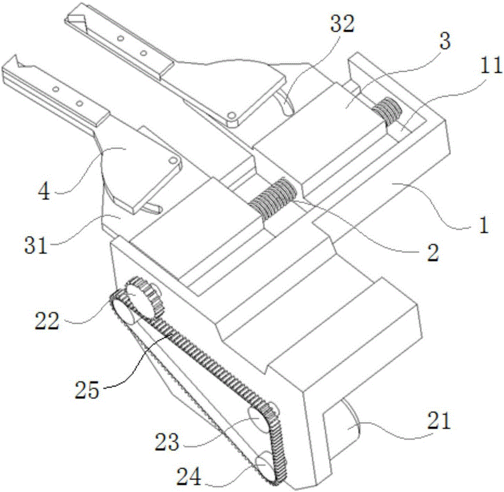
[0018] Such as figure 1 As shown, an embodiment according to a specific embodiment of the present invention is: a self-locking clamping manipulator, which includes a frame 1, a transverse chute 11, a screw rod 2, a slide table 3, jaws 4, and a holding mechanism ,in:

[0019] The frame 1 is provided with a transverse chute, and the screw mandrel 2 is arranged in the transverse chute 11 in a rotatable manner. The left and r...


PUM


Abstract

The invention discloses a self-locking clamping manipulator. The self-locking clamping manipulator comprises a rack, a screw rod, two sliding tables, two clamping jaws and a driving mechanism, wherein the rack is provided with a transverse sliding groove; the screw rod is arranged in the transverse sliding groove in a rotating mode; the left side and the right side of the screw rod are each provided with a threaded part, and the threaded parts on the left side and the right side of the screw rod are opposite in thread turning direction; the two sliding tables are arranged in the transverse sliding groove in the mode that the two sliding tables can slide leftwards and rightwards; each sliding table is in engaged connection with one threaded part of the screw rod through a threaded hole; the rear ends of the two clamping jaws are arranged on the sliding tables respectively; the driving mechanism is used for driving the screw rod to rotate. The self-locking clamping manipulator is simple and compact in structure, the operation space for the two clamping jaws is large, actions are flexible, position locating is accurate, and reliability is high.

Description

technical field [0001] The invention relates to the field of manipulators, in particular to a self-locking clamping manipulator. Background technique [0002] Manipulator is a high-tech automatic production equipment developed in recent years. It can replace human beings to carry out heavy labor to realize mechanization and automation of production, and can operate in harmful environments to protect personal safety. And the unique advantages of the machine, so it is widely used in machinery manufacturing, metallurgy, electronics, light industry and atomic energy and other departments. The manipulator has broad application and development prospects in various fields of the national economy. [0003] The existing clamping manipulator is an automatic operation device for grabbing, carrying objects or operating tools. It is often controlled by hydraulic pressure or air pressure. Small space. [0004] The information disclosed in this Background section is only for enhancing th...

Claims


Application Information

Patent Timeline
Patent Type & Authority Applications(China)
IPC IPC(8): B25J13/00B25J15/00
CPCB25J13/00B25J15/00
Inventor 李海波
Owner GUANGXI UNIV
Why Eureka
Try Eureka