
Chain saw and control method thereof

A control method, chain saw technology, applied to chain saws, electrical program control, program control in sequence/logic controllers, etc., can solve the problems of difficult installation of electronic components, poor operability, disadvantages, etc., and achieve low cost , Simple structure, accurate prevention effect

Inactive Publication Date: 2015-11-25
POSITEC POWER TOOLS (SUZHOU) CO LTD
View PDF5 Cites 3 Cited by
  • Summary
  • Abstract
  • Description
  • Claims
  • Application Information

AI Technical Summary

Problems solved by technology

If the electronic sensing unit is set closer to the center of rotation, the signal detected by the electronic sensing unit will be weak, which is not conducive to accurately judging the occurrence of the "kickback" phenomenon
If the electronic sensing unit is set far from the center of rotation, such as on a guide plate, the signal detected by the electronic sensing unit is relatively strong, but another problem is that it is difficult to install electronic components on the guide plate, and the operability is not strong

Method used


Image

  • Chain saw and control method thereof
  • Chain saw and control method thereof
  • Chain saw and control method thereof

Examples


Embodiment Construction

[0039] The preferred embodiments of the present invention will be described in detail below in conjunction with the accompanying drawings, so that the advantages and features of the present invention can be more easily understood by those skilled in the art, so as to define the protection scope of the present invention more clearly.

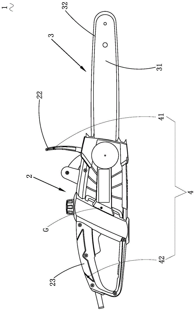
[0040] Such as figure 1 Shown is a chainsaw 1 according to one embodiment of the invention. The chain saw 1 mainly includes a housing 2 and a working assembly 3 that performs cutting work. Housing 2 is hollowly provided with, and its inside is provided with motor 21 ( figure 1 not shown). The motor 21 is used to drive the working component 3 to perform work. A transmission mechanism not shown in the figure is also provided in the housing 2 . In a preferred embodiment, the housing 2 further includes a handle device 23 for gripping and a front baffle 22 between the handle device 23 and the working assembly 3 . The front baffle 22 is closer to ...


PUM


Abstract

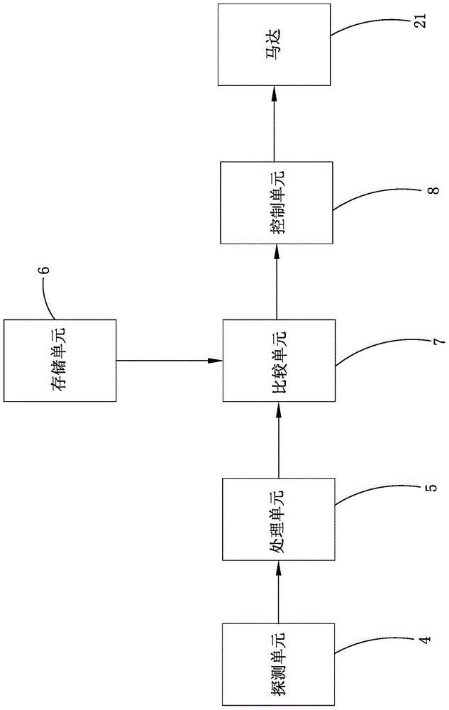
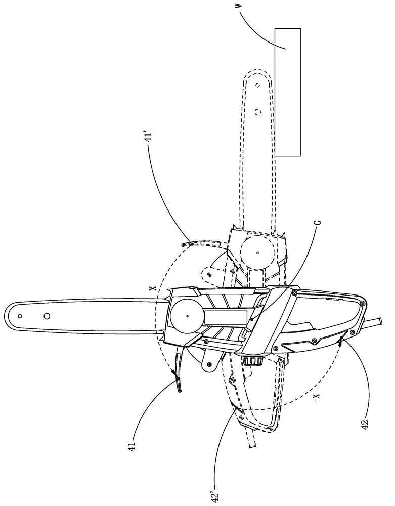
The invention relates to a chain saw. The chain saw comprises a shell, a working subassembly, a motor, at least two detection units, a processing unit, a storage unit, a comparison unit and a control unit, wherein the working subassembly stretches out of the shell along the longitudinal direction; the motor is contained in the shell and is used for driving the working subassembly to carry out cutting work; two of the at least two detection units are respectively arranged at two sides of the gravity center of the chain saw and are used for detecting a moving condition of the positions where the two detection units are located and generating detection signals; the processing unit is used for receiving the detection signals and generating an intermediate signal; the storage unit is used for storing a preset reference signal; the comparison unit is used for comparing the intermediate signal with the preset reference signal; the control unit is used for outputting a control signal to control the working subassembly to stop the cutting work under a preset condition according to a comparison result of the comparison unit.

Description

technical field [0001] The invention relates to a power tool, in particular to a chain saw and a control method thereof. Background technique [0002] As a portable cutting tool, the chain saw is used in various scenes such as cutting wood and carving statues. Because of its cutting efficiency and strong cutting ability, it is widely welcomed. According to the survey, most users have relatively little experience in using chainsaws, are not very familiar with the relevant protective measures of chainsaws, and are not very familiar with the safe operation of chainsaws, which leads to reports of injuries caused by improper use of chainsaws every year. happens sometimes. One of the most dangerous things to do when a chainsaw is in operation is the phenomenon known as "kickback" or "kickback". "Kickback" means that when the working components at the front end of the chain saw (mainly referring to the chain rotating around the guide plate) cut logs or branches and other objects...

Claims


Application Information

Patent Timeline
Patent Type & Authority Applications(China)
IPC IPC(8): B27B17/00G05B19/04
Inventor 强尼·鲍瑞那图
Owner POSITEC POWER TOOLS (SUZHOU) CO LTD
Learn More