
A method for starting a drain valve and a starting mechanism using the method

A start-up mechanism and drain valve technology, which is applied to flushing equipment with water tanks, water supply devices, buildings, etc., can solve problems such as bad hand feeling, large operating force, and affecting user experience, so as to achieve good operating feel and low operating force , the effect of simple structure

Active Publication Date: 2017-05-24
XIAMEN R&T PLUMBING TECH
View PDF8 Cites 0 Cited by
  • Summary
  • Abstract
  • Description
  • Claims
  • Application Information

AI Technical Summary

Problems solved by technology

Therefore, the existing drain valve requires a lot of operating effort during the entire operation process of starting the drain, which affects the user's experience and feels bad.

Method used


Image

  • A method for starting a drain valve and a starting mechanism using the method
  • A method for starting a drain valve and a starting mechanism using the method
  • A method for starting a drain valve and a starting mechanism using the method

Examples


Embodiment 1

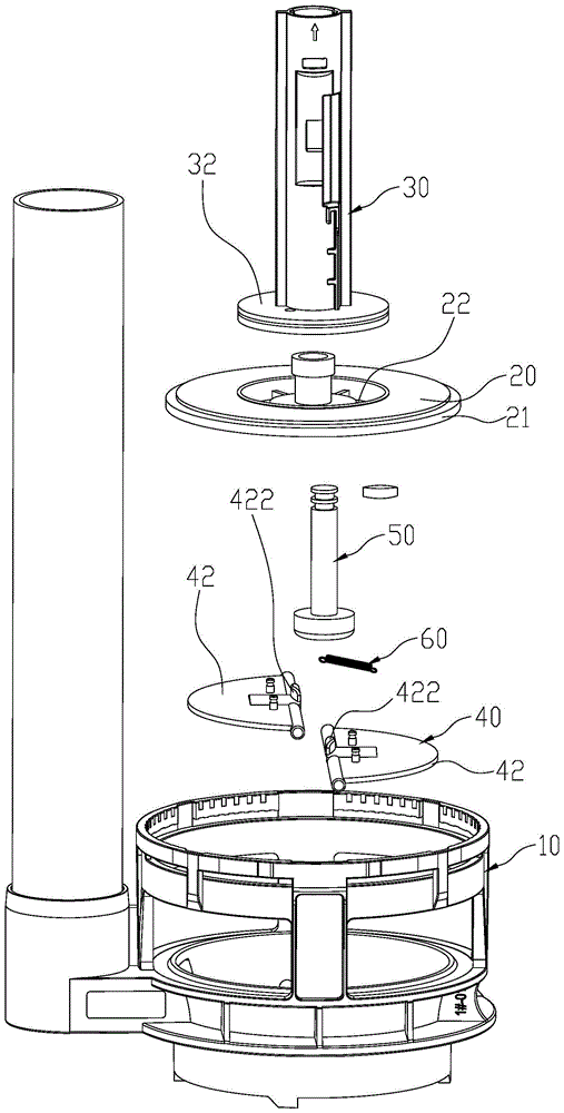
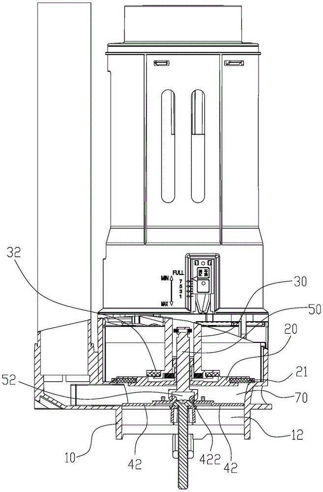
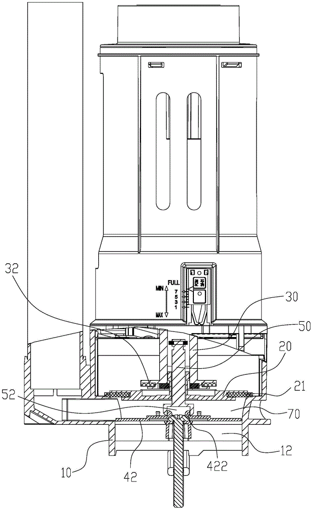
[0034] Please refer to figure 1 and figure 2 , a drainage valve activation mechanism of the present invention, including a base 10 , a water stop plate 20 , an activation rod 30 , a water retaining plate 40 , a control member 50 , and an elastic member 60 .

[0035] The base 10 is provided with a drainage channel 12 . The water stop plate 20 is used to cover the top opening of the drain channel 12, and a water stop rubber pad 21 is fixed on the water stop plate 20, which is used to seal the drain channel 12 when the drain valve is closed, preventing water from entering the drain channel. Inside channel 12. A through hole 22 is formed vertically in the middle of the water stop plate 20 . The activation rod 30 can vertically reciprocate and is used to open the water stop plate 20 . An end cap 32 for covering the through hole 22 extends outwardly from the bottom of the activation rod 30 .

[0036] The water deflector 40 is disposed in the drainage channel 12 . The water ba...

Embodiment 2

[0043] Please refer to Image 6 and Figure 7 The difference between the second embodiment and the first embodiment is that: the bottom of the outer edge of the leaf 42a is pivotally connected with the base 10, and the middle of the inner edge of the leaf 42a is provided with a socket 424; the bottom surface of the control member 50a An insertion rod 54 is provided on the top, and the insertion rod 54 is inserted into the two insertion holes 424 when the water shield is in a closed state, so as to prevent the two leaf pieces 42a from turning downwards and opening.

[0044] When the control member 50a moves upward and the plunger 54 is pulled out from the insertion hole 424, the water pressure acts on the leaf 42a to open the leaf 42a. The elastic member can be connected between the base 10 and the leaf 42a, so that the leaf 42a can automatically reset to a horizontally closed state after being opened.

Embodiment 3

[0046] Please refer to Figure 8 The difference between Embodiment 3 and Embodiment 1 is that: the water retaining plate 40b is vertically reciprocated and arranged in the drainage channel 12, the water retaining plate 40b is connected to the bottom end of the control member 50b, and the water retaining plate 40b and the control member 50b are integrally formed. When the control member 50b moves up and out of the drainage channel 12 , the water can be quickly discharged from the drainage channel 12 .


PUM


Abstract

The invention discloses a method and a mechanism for starting a drain valve. The mechanism for starting the drain valve comprises a base with a drain channel, a water stopping disc, a water stopping rubber mat, a starting rod and a water barrier. The water stopping disc is used for covering the drain channel, the water stopping rubber mat is fixedly connected onto the water stopping disc and is used for sealing the drain channel, the starting rod can vertically reciprocate and is used for lifting the water stopping disc, the water barrier is arranged in the drain channel and can be in a closed state or a released state by means of switching in a reciprocating manner, a water storage cavity is enclosed by the water barrier in the closed state, the drain channel and the water stopping disc, the drain channel can be opened when the water barrier is in the released state, and water in the water storage cavity can be drained. The method and the mechanism have the advantages that when the drain valve is started, the water storage cavity is filled with the water at first, so that water pressures on the bottom surface of the water stopping disc can be offset by water pressures on the top surface of the water stopping disc, then the water stopping disc can be lifted by the aid of little force, an operating force value of the drain valve can be reduced, and the mechanism is good in operating hand feel.

Description

technical field [0001] The invention relates to a method for starting a drain valve and a starting mechanism using the method. Background technique [0002] When the existing drain valve is started, the water pressure directly acts on the water stop plate. During the whole process of opening the drain valve for drainage, the water stop plate bears the downward pressure from the water above it for a long time; at the same time, In the initial stage of start-up, the water stop pan will also be subjected to the downward suction of the water below it. Therefore, the existing drain valve requires a lot of operating effort during the entire operation process of starting the drain, which affects the user's experience and feels bad. Contents of the invention [0003] The invention provides a drain valve starting method and a starting mechanism adopting the method, which overcome the shortcomings of the background technology. The technical solution adopted by the present inventio...

Claims


Application Information

Patent Timeline
Patent Type & Authority Patents(China)
IPC IPC(8): E03D5/092E03D1/34
Inventor 江力陈海滨周洪文
Owner XIAMEN R&T PLUMBING TECH
Learn More