Method for obtaining CO2 fluid longitudinal wave time difference framework parameters of high-temperature and high-pressure reservoir

A technology of longitudinal wave transit time, high temperature and high pressure, which is applied in the field of oil and gas exploration, can solve the problems of low accuracy of longitudinal wave transit time frame parameters, low precision of porosity parameters, and large value difference, etc. Effect

Active Publication Date: 2015-11-25
CHINA NAT OFFSHORE OIL CORP +1
View PDF7 Cites 3 Cited by
  • Summary
  • Abstract
  • Description
  • Claims
  • Application Information

AI Technical Summary

Problems solved by technology

Most of the existing methods for obtaining skeleton parameters of carbon dioxide fluid compressional wave transit time are to query the charts recorded in relevant literature, roughly obtain relevant parameters from the charts, and use them as skeleton parameter values ​​for logging interpretation. However, in long-term production practice, technical The personnel found that the accuracy of the carbon dioxide fluid compressional wave transit time frame parameters obtained by the above method is low, which leads to the low accuracy of the porosity parameters obtained by using the acoustic logging data for logging processing and interpretation. The main reason is that this method is relatively subjective. There are some estimation processes; thus, the skeleton parameters of carbon dioxide fluid P-wave transit time differ greatly from the values ​​in the actual formation

Method used


Image

  • Method for obtaining CO2 fluid longitudinal wave time difference framework parameters of high-temperature and high-pressure reservoir
  • Method for obtaining CO2 fluid longitudinal wave time difference framework parameters of high-temperature and high-pressure reservoir
  • Method for obtaining CO2 fluid longitudinal wave time difference framework parameters of high-temperature and high-pressure reservoir

Examples


Embodiment Construction

[0024] In order to better understand the above-mentioned technical solution, the above-mentioned technical solution will be described in detail below in conjunction with the accompanying drawings and specific implementation methods.

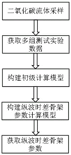
[0025] The invention provides a high temperature and high pressure reservoir CO 2 A method for obtaining skeleton parameters of fluid compressional wave transit time, which can significantly improve the accuracy of obtaining carbon dioxide fluid skeleton longitudinal wave transit time parameters, and then improve the accuracy of logging interpretation and evaluation porosity of high-temperature and high-pressure carbon dioxide-rich gas layers calculated by using acoustic logging data, It has strong versatility. The invention provides a better and quicker acquisition method for the selection of carbon dioxide fluid skeleton compressional wave transit time parameters in logging interpretation and evaluation of high-temperature and high-pressure gas...


PUM


Abstract

The invention provides a method for obtaining CO2 fluid longitudinal wave time difference framework parameters of a high-temperature and high-pressure reservoir. The method comprises the step S1 of sampling CO2 fluid; the step S2 of obtaining multiple groups of test experimental data; on the conditions of different temperature and pressure, performing determination tests of longitudinal wave speed on CO2 fluid samples and obtaining multiple groups of data formed by longitudinal wave speed parameters, temperature parameters and pressure parameters; the step S3 of establishing a primary calculation model; the step S4 of establishing a longitudinal wave time difference framework parameter calculation model; and the step S5 of obtaining the longitudinal wave time difference framework parameters. By utilizing the method, the accuracy of obtaining the CO2 fluid longitudinal wave time difference framework parameters can be remarkably improved, the accuracy of calculating well logging interpretation evaluation porosity of a high-temperature and high-pressure gas reservoir rich in CO2 by means of acoustic logging information is improved, and the method is high in universality. The better and quicker obtaining method is provided for selection of the CO2 fluid longitudinal wave time difference framework parameters in high-temperature and high-pressure gas reservoir well logging interpretation.

Description

technical field [0001] The invention relates to the technical field of oil and gas exploration, in particular to a high-temperature and high-pressure reservoir CO 2 A method for obtaining skeleton parameters of fluid longitudinal wave transit time. Background technique [0002] In the process of logging interpretation and evaluation of high-temperature and high-pressure carbon dioxide-rich gas reservoirs, logging technicians are required to perform timely logging interpretation on the obtained downhole acoustic logging data based on the formation component volume model to obtain the porosity parameters of the gas reservoirs. The key is to determine the carbon dioxide fluid compressional wave transit time frame parameters under formation conditions. Most of the existing methods for obtaining skeleton parameters of carbon dioxide fluid compressional wave transit time are to query the charts recorded in relevant literature, roughly obtain relevant parameters from the charts, a...

Claims


Application Information

Patent Timeline
Patent Type & Authority Applications(China)
IPC IPC(8): E21B47/00
Inventor 谢玉洪周家雄何胜林张海荣
Owner CHINA NAT OFFSHORE OIL CORP
Why Eureka
Try Eureka