Rotation machine axial force testing apparatus and testing method thereof

A technology for rotating machinery and testing devices, applied in the field of rotating machinery, can solve the problems of measurement difficulty, inconvenience, and inability to accurately measure axial force, etc., and achieve the effects of easy popularization and application, wide versatility, and simple structure

Active Publication Date: 2015-11-25
GUANGDONG KENFLO PUMP CO LTD +1
View PDF10 Cites 35 Cited by
  • Summary
  • Abstract
  • Description
  • Claims
  • Application Information

AI Technical Summary

Problems solved by technology

[0006] At present, the axial force measurement methods include the tension-pressure sensor method and the spring balance measurement method. The tension-pressure sensor method is based on the structure of the centrifugal pump, and the tension-pressure sensor is directly installed on the gland of the centrifugal pump, and the tension piston is connected to the pump rotor. Through it, the axial force is transmitted to the tension and pressure sensor, and then the force is converted into an electrical signal to measure the axial force; the spring scale measurement method is that the bearing seat is fixed on the stator and does not move, and the bearing sleeve and the right bearing seat are clearance...

Method used


Image

  • Rotation machine axial force testing apparatus and testing method thereof
  • Rotation machine axial force testing apparatus and testing method thereof
  • Rotation machine axial force testing apparatus and testing method thereof

Examples


Embodiment 1

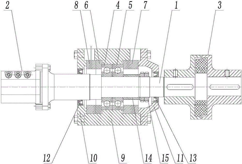
[0034] figure 1 It is a structural schematic diagram of Embodiment 1 of the present invention, which is used to measure the axial force in the direction of the first bearing. Such as figure 1 As shown, an axial force testing device for a rotating machine includes a housing, a bearing, a rotating shaft 1 and a sensor, the rotating shaft 1 is fixedly connected to the inner ring of the bearing, the outer ring of the bearing is fixedly connected to the housing, and is fitted on the rotating shaft 1 The sensor, the output signal of the sensor is electrically connected to the signal processing device, the rotating shaft 1 and the rotating machine adopt a keyless connection, and the rotating shaft and the motor are connected by a coupling.

[0035] The rotating shaft 1 is a stepped rotating shaft, one side of the inner ring of the bearing leans against the step of the rotating shaft 1, and the other side is fixed by the shaft sleeve 14 and the lock nut 15, so as to realize axial fas...

Embodiment 2

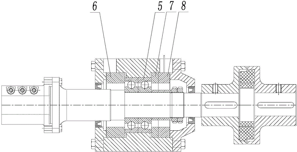
[0041] image 3 It is a structural schematic diagram of Embodiment 2 of the present invention, which is used to measure the axial force in the direction of the second bearing. Such as image 3 As shown, the sensor 8 of the second embodiment is arranged outside the outer ring of the second bearing 5 , and the second compensation ring 7 is arranged between the second bearing 5 and the sensor 8 . Other configurations of the second embodiment are the same as those of the first embodiment, and will not be repeated here.

Embodiment 3

[0043] Figure 4 It is a structural schematic diagram of Embodiment 3 of the present invention, which is used to measure the axial force in the first bearing direction and the second bearing direction. Such as Figure 4 As shown, the bearing of the third embodiment includes the first bearing 4 and the second bearing 5 that are close together. The bearing of the third embodiment is an angular contact ball bearing, which is characterized in that it can bear a large axial force and has directional , equipped with two bearings can adapt to the axial force requirements in two directions; the sensor is two sensors, including the first sensor 8 and the second sensor 16, the first sensor 8 is set outside the outer ring of the first bearing 4, and the second The outer side of the outer ring of the second bearing 5 is provided with a second sensor 16, a first compensation ring 6 is provided between the first bearing 4 and the first sensor 8, and a second compensation ring 7 is provided...


PUM


Abstract

The invention relates to the technical field of a rotation machine, more particularly to a rotation machine axial force testing apparatus and a testing method thereof. The apparatus comprises a housing, a bearing, a rotation shaft and a sensor. The rotation shaft is fixedly connected to the inner ring of the bearing. The outer ring of the bearing is fixedly connected with the housing. The rotation shaft is sleeved by the sensor. Signals outputted from the sensor are electrically connected to a signal processing device; the rotation shaft and a rotation machine are connected through a keyless connection component and the rotation shaft is connected with a motor through a shaft coupler. The apparatus has great universality to test the axial force of a variety of rotation machines. The apparatus can also carry out/perform in one direction or two directions with a 1% range error tolerance. Simple in structure, the apparatus is an independent device and is convenient to install. When in use, a rotation machine needs not to be modified. Capable of providing an effective means to problems of axial force balance among various machines, the apparatus and method can be promoted for wider applications.

Description

technical field [0001] The invention relates to the field of rotating machinery, in particular to an axial force testing device and a testing method for the rotating machinery. Background technique [0002] Various rotating machinery such as water pumps, fans, compressors, blowers, steam turbines, etc., the blades will generate axial force due to the action of the medium during the rotating process. Take the water pump as an example. During the operation of the vane type water pump, the water flows through the impeller to do work and becomes high-pressure water, which generates a water pressure difference between the front and rear of the impeller. The water pressure difference and hydraulic dynamic reaction force are the main factors for the axial force of the pump rotor. , and the axial force will have an adverse effect on bearing life, running stability, and mechanical loss; in the product design process, it is necessary to consider setting up components that balance the ...

Claims


Application Information

Patent Timeline
IPC IPC(8): G01L5/00
Inventor 刘世龙王维林区国惟招广志邬江
Owner GUANGDONG KENFLO PUMP CO LTD
Why Eureka
Try Eureka