A gear local fault diagnosis method and system

A local fault and diagnosis method technology, which is applied in the direction of machine gear/transmission mechanism testing, etc., can solve problems such as easy failure, and achieve the effects of wide application range, avoiding low-frequency interference, and accurate diagnosis results

Active Publication Date: 2018-10-02
KUNMING UNIV OF SCI & TECH
View PDF6 Cites 0 Cited by
  • Summary
  • Abstract
  • Description
  • Claims
  • Application Information

AI Technical Summary

Problems solved by technology

However, this method is prone to failure when the meshing harmonics are far away from the resonance region

Method used


Image

  • A gear local fault diagnosis method and system
  • A gear local fault diagnosis method and system
  • A gear local fault diagnosis method and system

Examples


Embodiment 1

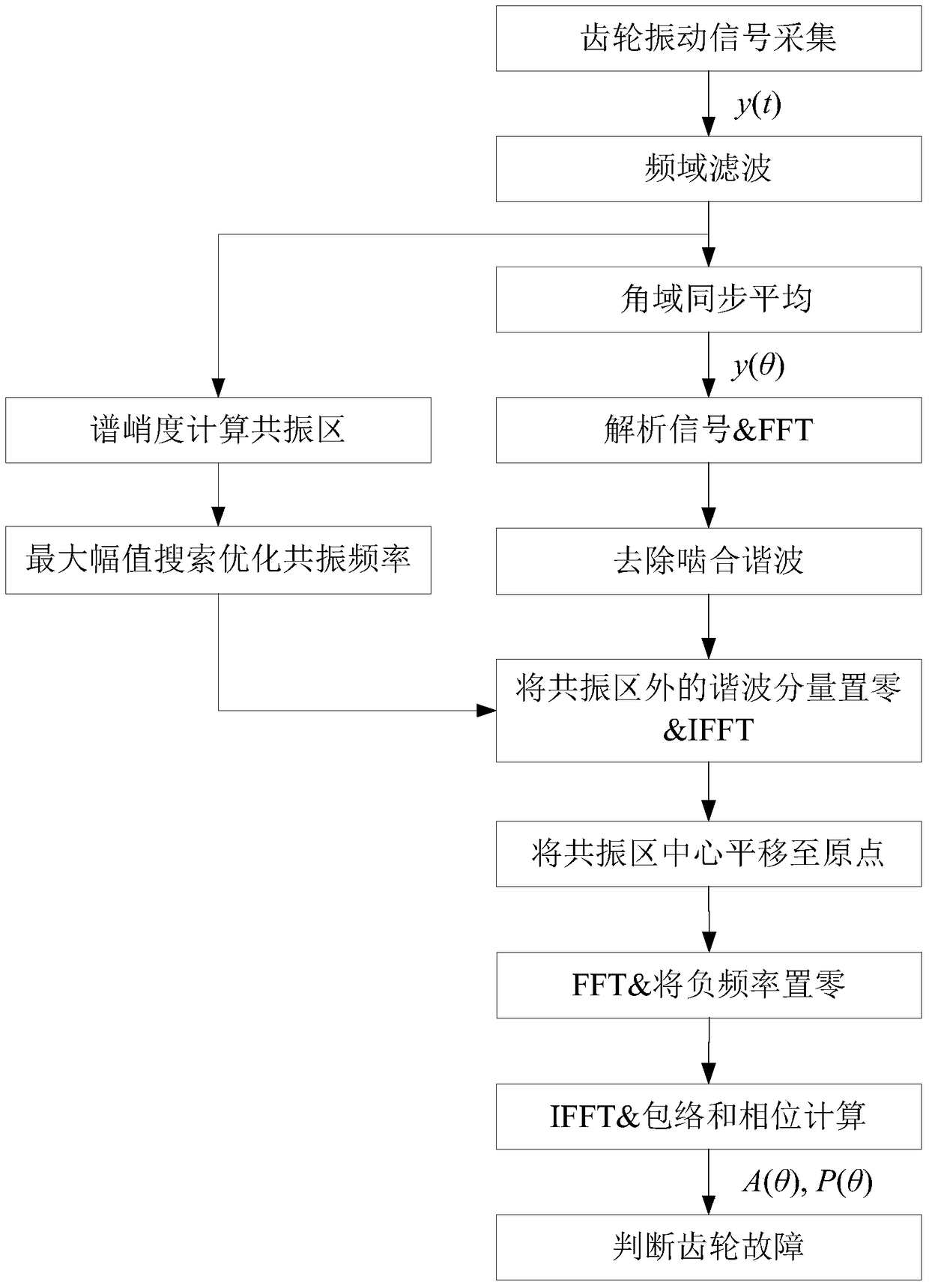
[0038] Embodiment 1: as Figure 1-4 As shown, a gear local fault diagnosis method, including:

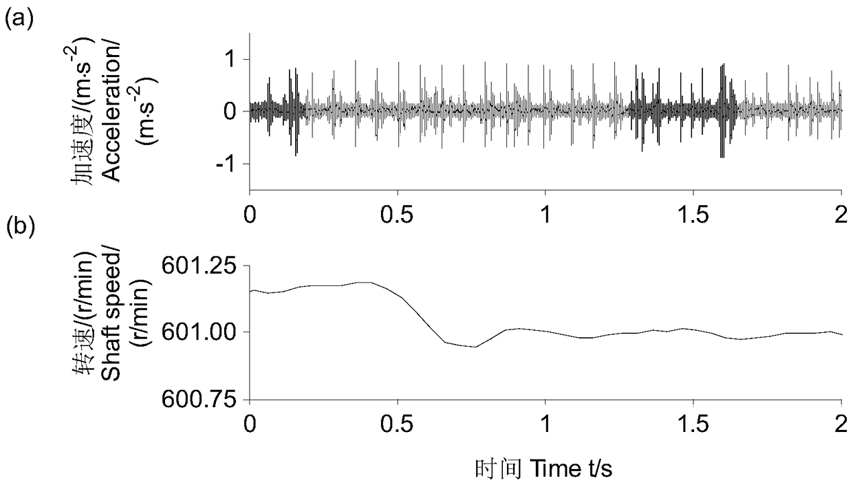
[0039] The signal acquisition step is to obtain the vibration signal of the faulty gear through the piezoelectric vibration acceleration sensor, and obtain the speed pulse signal of the shaft where the faulty gear is located through the eddy current displacement sensor;

[0040] The frequency domain filtering step is to perform band-pass filtering and noise reduction processing on the faulty gear vibration signal obtained in the signal acquisition step;

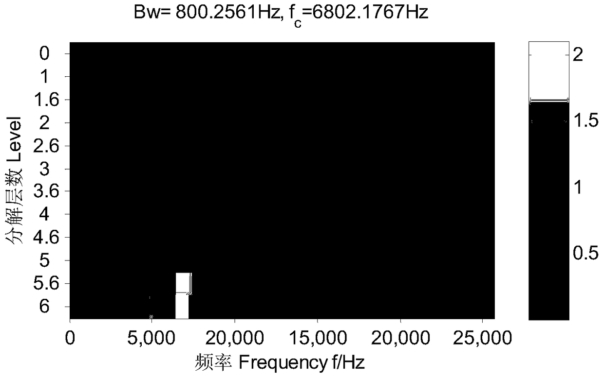
[0041] The spectral kurtosis calculation step is to calculate the optimal resonance frequency band {f o ,B o}, f o is the optimum resonant frequency, B o is the optimal bandwidth;

[0042] Angle-domain synchronous averaging step, the initial noise-reduced fault gear vibration signal obtained by the frequency-domain filtering step is converted into the angle domain and averaged to obtain the averaged angle-domain fault gear vib...

Embodiment 2

[0052] Embodiment 2: as Figure 1-4 Shown, basically the same as embodiment 1, on the basis of embodiment 1:

[0053] The frequency domain filtering step is specifically as follows: first transform the vibration signal of the faulty gear into the frequency domain through FFT, then set all the spectral lines outside the analysis frequency band (preferably 200-8000Hz) to zero, and then perform IFFT transformation to obtain a preliminary noise-reduced fault Gear vibration signal.

[0054] The spectral kurtosis calculation step is specifically: after the fault gear vibration signal of the preliminary noise reduction is obtained through the frequency domain filtering step, the fast spectral kurtosis diagram is used to calculate it to obtain the resonance frequency band {f c ,B c}, f c is the resonant frequency, B c is the bandwidth; use the maximum amplitude search method to search for the resonance frequency band {f c ,B c}, the frequency corresponding to the maximum amplitu...

Embodiment 3

[0061] Embodiment 3: as Figure 1-4 Shown, basically the same as embodiment 1, on the basis of embodiment 1:

[0062] The frequency domain filtering step is specifically as follows: first transform the vibration signal of the faulty gear into the frequency domain through FFT, then set all the spectral lines outside the analysis frequency band (preferably 200-8000Hz) to zero, and then perform IFFT transformation to obtain a preliminary noise-reduced fault Gear vibration signal.

[0063] The spectral kurtosis calculation step is specifically: after the fault gear vibration signal of the preliminary noise reduction is obtained through the frequency domain filtering step, the fast spectral kurtosis diagram is used to calculate it to obtain the resonance frequency band {f c ,B c}, f c is the resonant frequency, B c is the bandwidth; use the maximum amplitude search method to search for the resonance frequency band {f c ,B c}, the frequency corresponding to the maximum amplitu...


PUM


Abstract

The invention relates to a method and a system for diagnosing a local fault of a gear, and belongs to the field of fault diagnosis technologies and signal processing and analyzing technologies. The method comprises the steps of acquiring faulted gear vibration signals and rotating speed pulse signals of a shaft where a faulted gear is located; carrying out band-pass filtering and de-noising processing on the acquired faulted gear vibration signals; calculating an optimal resonant frequency band of the preliminarily de-noised faulted gear vibration signals; converting the acquired preliminarily de-noised faulted gear vibration signals into an angular domain, and carrying out average processing so as to acquire averaged angular domain faulted gear vibration signals; removing signal components except for the optimal resonant frequency band in the averaged angular domain faulted gear vibration signals by using the acquired optimal resonant frequency band, and acquiring faulted gear fault feature signals; and carrying out demodulation analysis on the acquired faulted gear fault feature signals by using envelope analysis and phase calculation. The method and the system provided by the invention can better ensure the precision of extracted gear fault information.

Description

technical field [0001] The invention relates to a gear local fault diagnosis method and system, belonging to the technical field of fault diagnosis technology and signal processing and analysis. Background technique [0002] Narrowband demodulation technology is one of the traditional gear fault diagnosis technologies. This technology uses the low-order meshing harmonic with large amplitude as a demodulation analysis method. It demodulates the amplitude and phase modulation information at the same time. Judgment gear fault information. However, it is susceptible to low-frequency interference. Its improved algorithm-resonant narrowband demodulation analysis avoids the influence of low frequency interference. However, this method is prone to failure when the meshing harmonics are far away from the resonance region. Resonance demodulation analysis is a classic bearing fault diagnosis method. It was later used in the diagnosis and analysis of early faults of gears, but it is...

Claims


Application Information

Patent Timeline
Patent Type & Authority Patents(China)
IPC IPC(8): G01M13/02
Inventor 郭瑜孙守保伍星刘畅贺玮谢金葵
Owner KUNMING UNIV OF SCI & TECH
Why Eureka
Try Eureka