Method for measuring and determining micro-seismic focus

A micro-earthquake and source technology, which is applied in the fields of disasters, resources and environment, and can solve the problems of frequency characteristic variation, amplitude and energy distortion, and failure to achieve superposition.

Active Publication Date: 2015-11-25
CHINA UNITED COALBED METHANE +1
View PDF7 Cites 10 Cited by
  • Summary
  • Abstract
  • Description
  • Claims
  • Application Information

AI Technical Summary

Problems solved by technology

Analysis C shows that the amplitude and energy are severely distorted, and the frequency characteristics bec

Method used


Image

  • Method for measuring and determining micro-seismic focus
  • Method for measuring and determining micro-seismic focus
  • Method for measuring and determining micro-seismic focus

Examples


Embodiment Construction

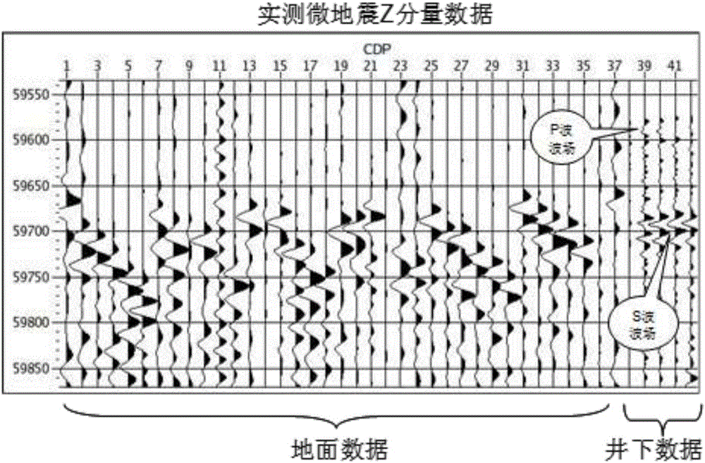
[0037] image 3It is the measured surface and well Z component data of hydraulic fracturing microseismic. The data has been filtered and normalized. It can be seen that the S-wave field data in the well is basically similar to the P-wave field data on the ground in terms of frequency characteristics, and the frequency range is roughly between 25-70Hz. The frequency of the P wave component in the well is relatively high, and due to the receiving direction of the geophone, the energy of the P wave is lower than that of the S wave; the surface data is also due to the Z component, and the energy level of the S wave is very low.

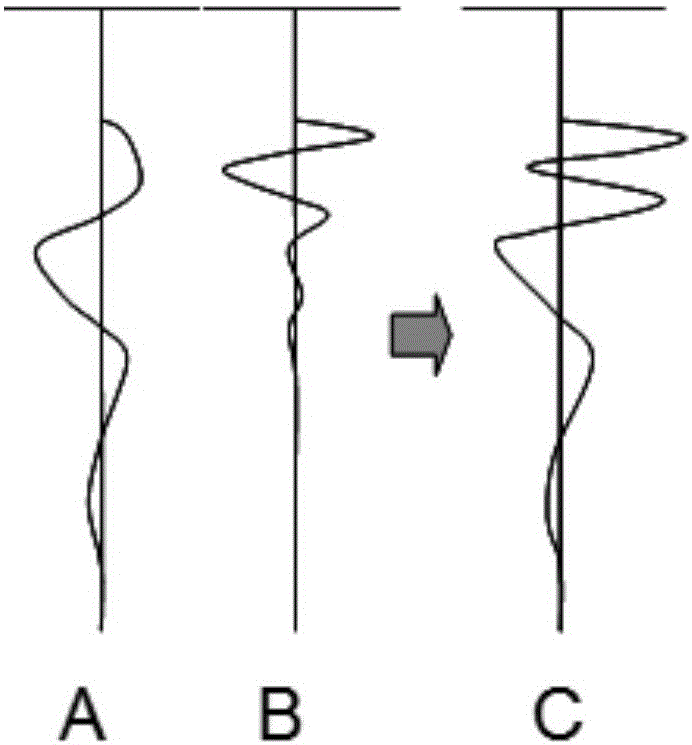
[0038] Figure 4 The arrangement of the above data after NMO is given. The best sign of microseismic event location is the first arrival alignment. It can be seen in the figure that the first main lobe of the peak corresponding to the surface and downhole data has been aligned; since the frequency characteristics of the surface P wave and downhole S wav...


PUM


Abstract

The invention relates to the disaster, resources and environment field, particularly to a method for measuring and determining a micro-seismic focus. The method comprises the steps of collection, pretreatment, first-motion picking up, division of to-be-measured underground space into fine volume meshes, NMO working, signal superposition, and coordinate point determination and the like. With the method, a defect that a maximum energy method can not be applied to down-hole micro-seismic data and ground micro-seismic data to determine a micro-seismic position can be overcome. According to the method, hydraulic fracturing micro-seismic data collected on the ground and data collected under the well are combined and the down-hole micro-seismic position is obtained based on joint inversion. The practical data inversion result demonstrates that the method provides a new way for obtaining a seismic focus position based on inversion by means of a maximum energy superposition method by using the combined ground and down-hole micro-seismic data.

Description

technical field [0001] The invention relates to the fields of disasters, resources and the environment, in particular to a method for measuring microseismic sources. Background technique [0002] The development of unconventional oil and gas fields requires hydraulic fracturing, which promotes the formation of network fractures in underground reservoirs and increases oil and gas production. The fractures formed by fracturing need to be imaged by using microseismic monitoring technology to evaluate the effect. At present, the conventional microseismic monitoring scheme is to deploy acoustic sensors in wells or on the ground to collect microseismic signals caused by hydraulic fracturing and position and image them. There are many schemes for positioning technology, among which the method of maximum energy superposition is favored by people. It is not only applied to microseismic wave propagation time, but also amplitude and phase characteristics. The smaller the difference ...

Claims


Application Information

Patent Timeline
IPC IPC(8): G01V1/30
Inventor 薛爱民吴建光艾建华张平李兴锋
Owner CHINA UNITED COALBED METHANE
Why Eureka
Try Eureka