An Optical Symbol Scanner

A technology of scanners and symbols, which is applied in the field of scanners, can solve the problems that the toughness of the shrapnel is easily weakened, and the swing speed of the swinger changes greatly, so as to achieve the effect of uniform swing speed

Active Publication Date: 2017-12-29
深圳市合杰电子有限公司
View PDF10 Cites 0 Cited by
  • Summary
  • Abstract
  • Description
  • Claims
  • Application Information

AI Technical Summary

Problems solved by technology

[0007] The technical problem to be solved by the present invention is to provide an optical symbol scanner, which aims to solve the problems of the optical symbol scanner in the prior art that the toughness of the shrapnel of the oscillator is easily weakened and the swing speed of the oscillator changes greatly

Method used


Image

  • An Optical Symbol Scanner
  • An Optical Symbol Scanner
  • An Optical Symbol Scanner

Examples


Embodiment Construction

[0026] In order to make the technical problems, technical solutions and beneficial effects to be solved by the present invention clearer, the present invention will be further described in detail below in conjunction with the accompanying drawings and embodiments. It should be understood that the specific embodiments described here are only used to explain the present invention, not to limit the present invention.

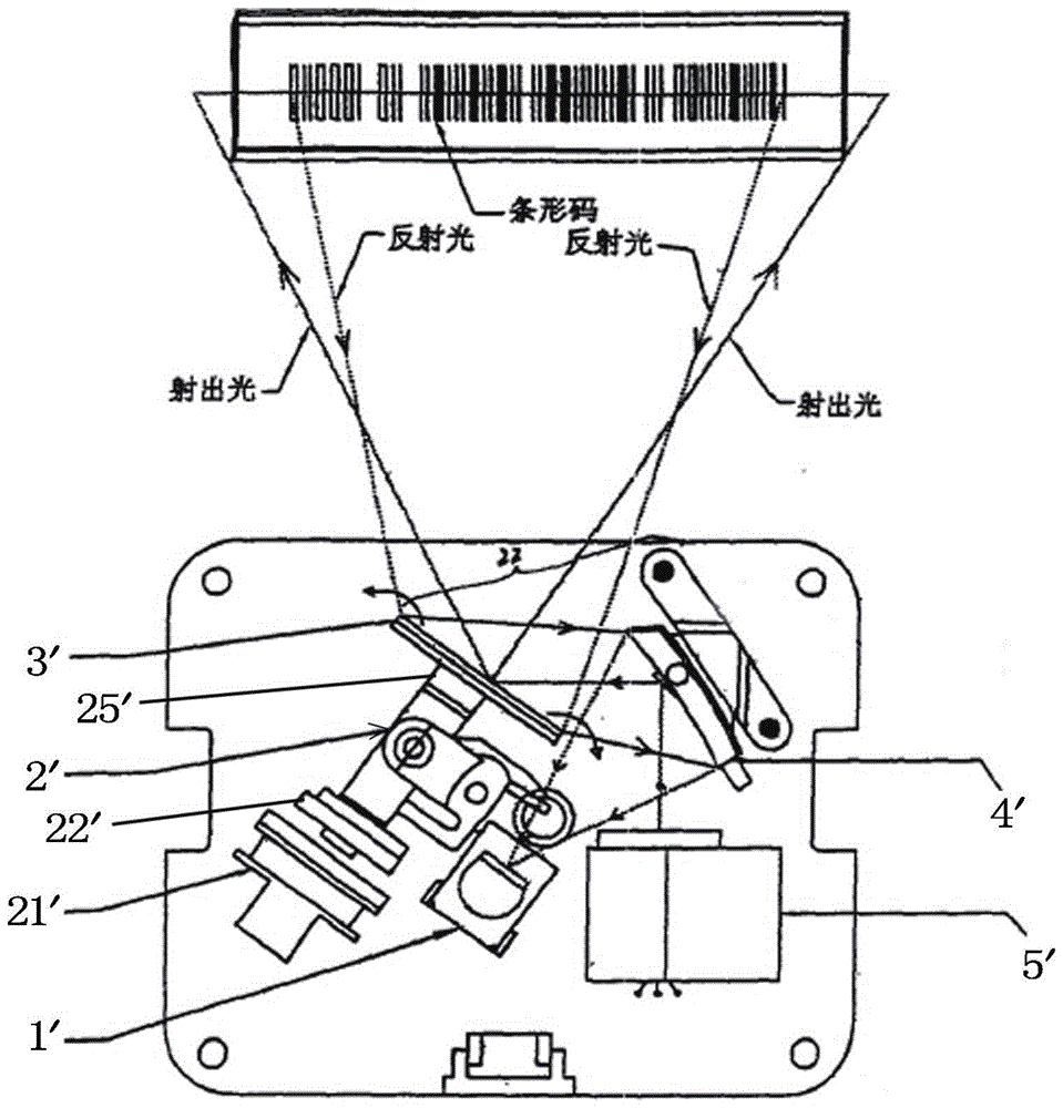
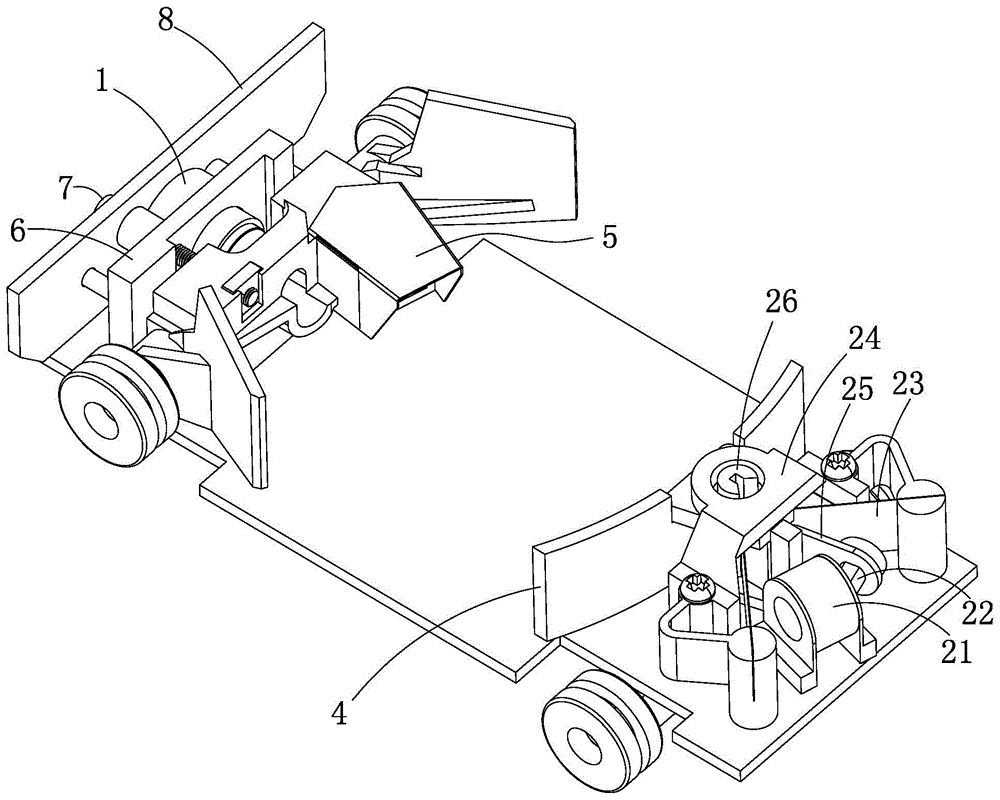
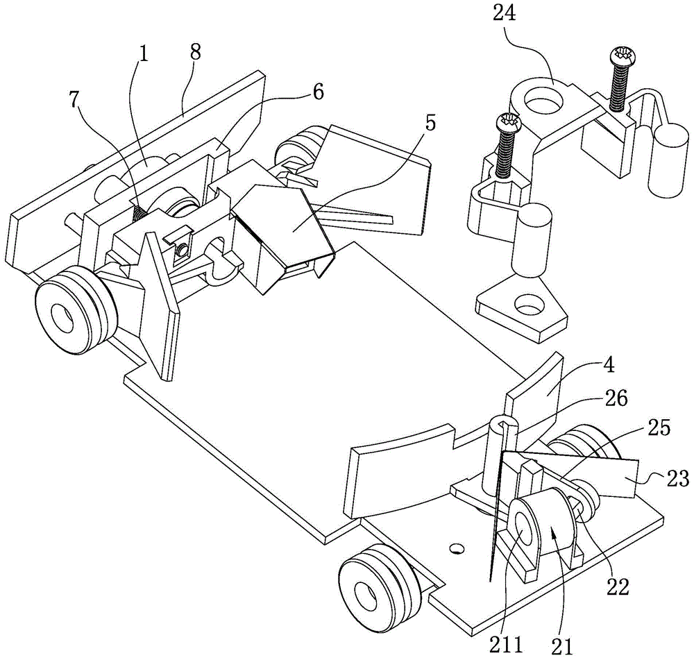
[0027] Such as Figure 2 to Figure 7 Shown is a preferred embodiment of the present invention, an optical symbol scanner, including a light source 1 , an oscillating device 2 , an oscillating mirror 3 , a collecting reflector 4 and a light receiver 5 . The oscillator 2 includes an electromagnetic coil 21 , a magnet 22 , an elastically deformable elastic piece 23 , a fixing base 24 , a swing member 25 and a turntable 26 .

[0028] The electromagnetic coil 21 and the magnet 22 are arranged close to each other. One end of the pendulum 25 is fixedly connected to the m...


PUM


Abstract

The invention is applicable to the technical field of scanners, and provides an optical symbol scanner. The optical symbol scanner comprises a light source, a swinging device, a swing mirror, a light collecting reflector and a light receiver. The swinging device comprises an electromagnetic coil, a magnet, an elastic piece capable of carrying out elastic deformation, a fixed base, a rotary table and a swinging member, wherein the electromagnetic coil is arranged close to the magnet, one end part of the swinging member is fixedly connected with the magnet, and the other end is in transmission connection with the rotary table; the rotary table is fixedly connected with the swing mirror; two ends of the elastic piece are fixed at two side edges of the fixed base respectively, the other end of the swinging member drives the rotary table to swing when the swinging member swings, and a middle part of the elastic piece is pulled at the same time. The elastic piece can pull the swinging member when the swinging member swings towards the left side and the right side, thereby enabling the swinging member to return to the original position. The pulling length of the elastic piece is only half of the pulling length of an elastic piece in a traditional oscillator, so that the toughness of the elastic piece is not easy to be weakened. In addition, the difference between pulling forces imposed on the swinging member by the elastic piece at an initial position and a final position is small, and the swinging speed is uniform.

Description

technical field [0001] The invention belongs to the technical field of scanners, in particular to an optical symbol scanner. Background technique [0002] Optical symbol scanners, such as barcode scanners, are now widely used in supermarkets and material warehouses to manage goods in a regular and efficient manner. [0003] See figure 1 , which is a structure of an optical symbol scanner in the prior art, which mainly includes a laser emitter 1' (light source), an oscillating device 2', an oscillating mirror 3', a collecting reflector 4' and a light receiver 5' . The oscillating device 2' includes an electromagnetic coil 21', a magnet 22', a plastic shrapnel (not shown in the figure) and a oscillating member 25'. The magnet 22' is fixedly connected with the pendulum mirror 3'. After the electromagnetic coil 21' is energized, the magnet 22' is attracted, so that the swing member 25' swings to a certain range within a certain angle range, and then the plastic shrapnel uses ...

Claims


Application Information

Patent Timeline
Patent Type & Authority Patents(China)
IPC IPC(8): G06K7/10
Inventor 杨天柱
Owner 深圳市合杰电子有限公司
Why Eureka
Try Eureka