Prepaid circuit breaker arc-extinguishing system

A circuit breaker, prepaid technology, applied in the direction of circuits, electrical components, electrical switches, etc., can solve the problems of poor isolation arc extinguishing effect, poor sealing, and insufficient safety, and achieve high safety and reliability, avoid short circuit, and good effect Effect

Inactive Publication Date: 2015-11-25
长城电器集团浙江科技有限公司
View PDF4 Cites 0 Cited by
  • Summary
  • Abstract
  • Description
  • Claims
  • Application Information

AI Technical Summary

Problems solved by technology

[0005] The arc extinguishing system in the existing circuit breaker has a complex struc

Method used


Image

  • Prepaid circuit breaker arc-extinguishing system
  • Prepaid circuit breaker arc-extinguishing system
  • Prepaid circuit breaker arc-extinguishing system

Examples


Embodiment Construction

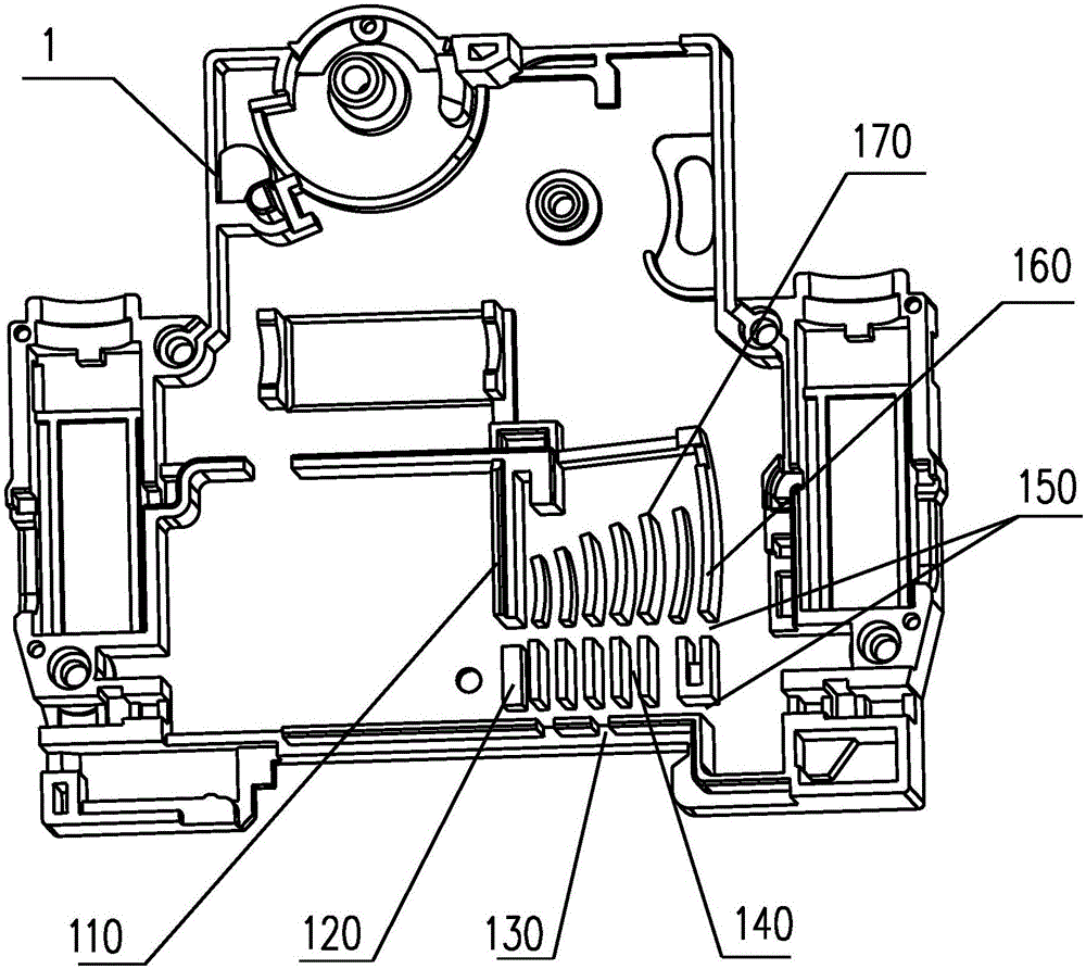
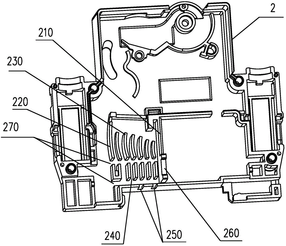
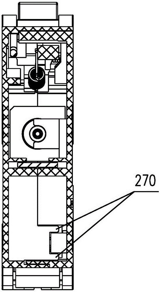
[0019] A prepaid circuit breaker arc extinguishing system, comprising a circuit breaker base 1 and a circuit breaker cover 2, the circuit breaker cover 2 is fixed on the circuit breaker base 1, and the inside of the circuit breaker base 1 is provided with a base Separation bar 170, base front isolation rib 110, base rear isolation rib 160, base lead groove 150, base positioning rib 120, base arc discharge groove 140, base arc discharge port 130, circuit breaker cover 2 The interior is provided with a cover dividing strip 230 corresponding to the inside of the circuit breaker base 1, a front isolation rib 210 of the cover, a rear isolation rib 220 of the cover, a lead wire groove 270 of the cover body, a positioning rib 260 of the cover body, and an arc discharge groove 240 of the cover body And the arc vent 250 of the cover body.

[0020] The circuit breaker cover 2 is covered on the circuit breaker base 1 , and a relatively sealed arc extinguishing system is formed between th...


PUM


Abstract

The invention discloses a prepaid circuit breaker arc-extinguishing system comprising a circuit breaker pedestal and a circuit breaker cover body. The circuit breaker cover body is fixed on the circuit breaker pedestal. The internal part of the circuit breaker pedestal is provided with pedestal segmentation strips, a pedestal front isolation rib, a pedestal rear isolation rib, a pedestal lead wire slot, a pedestal positioning rib, pedestal arc discharge slots and pedestal arc discharge ports. The internal part of the circuit breaker cover body is provided with cover body segmentation strips, a cover body front isolation rib, a cover body rear isolation rib, a cover body lead wire slot, a cover body positioning rib, cover body arc discharge slots and cover body arc discharge ports which are corresponding to the internal components of the circuit breaker pedestal. The beneficial effects are that the segmentation strips are corresponding in a staggered way so that arc can be effectively segmented, inter-arc voltage can be enhanced and arc can be extinguished, and isolation protection design is performed on an electronic control system so that ablation of arc to the electronic control line can be avoided; and a lead wire slot is designed on a shell for protecting a power supply wire so that short circuit caused by arc erosion can be avoided. The isolation and arc-extinguishing effect is great and safety and reliability are high.

Description


Claims


Application Information

Patent Timeline
Owner 长城电器集团浙江科技有限公司
Why Eureka
Try Eureka