Fault current limiter

一种故障电流、限制器的技术,应用在电气元件、电路装置、用于限制过电流/过电压的紧急保护电路装置等方向,能够解决FCL损坏、系统出现问题等问题,达到延长寿命的效果

Active Publication Date: 2015-11-25
LSIS CO LTD
View PDF6 Cites 1 Cited by
  • Summary
  • Abstract
  • Description
  • Claims
  • Application Information

AI Technical Summary

Problems solved by technology

This will most likely cause damage to the FCL and even cause problems with the system

Method used


Image

  • Fault current limiter
  • Fault current limiter
  • Fault current limiter

Examples


Embodiment Construction

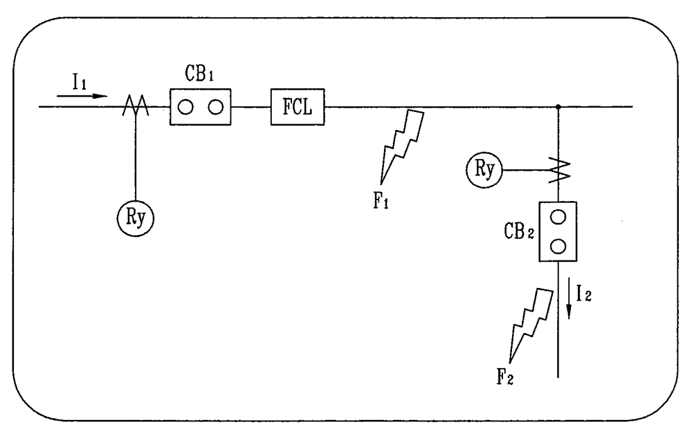
[0033] The invention disclosed herein is applicable to, but not limited to, a fault current limiter (FCL) that limits fault current flowing on a circuit or line. The technology disclosed herein can also be applied to any type of protection equipment to which the technical concept of the present invention can be applied, such as conventional switches, relays, surge absorbers, electronic contactors and circuit breakers, and can be applied to protection equipment included in in the current limiter circuit. In particular, FCL can be put into useful practice by being applied to monitoring equipment and protection equipment for protection circuits that require protection cooperation with systems and peripheral protection equipment.

[0034] It should be noted that the technical terms used herein are only used to describe specific embodiments, rather than to limit the present invention. Moreover, unless otherwise specified, technical terms used herein should be interpreted as meanin...


PUM


Abstract

This specification relates to fault current limiter (FCL). More particularly, to solve problems of protecting and designing current limiting impedance in a protective coordination system, as limitations of the related art, the fault current limiter may measure heat capacity of a current limiting impedance unit (200) by detecting fault current flowing to the current limiting impedance unit and limiting the fault current flowing to the current limiting impedance unit according to the measured heat capacity, which may result in preventing the current limiting impedance unit from being damaged due to the fault current, preventing an extended accident due to the damaged current limiting impedance unit and enabling a stabilized system and line protection.

Description

technical field [0001] This specification relates to fault current limiters, and more particularly, to a fault current limiter capable of preventing a fault current impedance unit from Damaged due to fault current. Background technique [0002] Typically, fault current limiters (FCLs) do not have their own blocking capability. Therefore, the FCL allows a limited fault current to flow until it is interrupted by a circuit breaker installed in the system. In a typical protective fit, such as figure 1 As shown, for the fault F2, the fault current should be blocked by the second circuit breaker CB2. When CB2 fails due to a problem, the first circuit breaker CB1 operates as backup protection. And, for the fault F1, the fault current is blocked by CB1. Therefore, the thermal capacity of a conventional FCL impedance is designed and manufactured even taking into account the blocking time taken by the backup protection through CB1 due to the failure of CB2. exist figure 1 In th...

Claims


Application Information

Patent Timeline
Patent Type & Authority Applications(China)
IPC IPC(8): H02H9/02
CPCH02H9/023H02H7/008H02H9/026Y02E40/60H02H9/00H02H9/02H02H7/001
Inventor 房承炫崔源寯金敃志安吉荣
Owner LSIS CO LTD
Why Eureka
Try Eureka