Charging system

A charging system and charger technology, applied in the direction of current collectors, electric vehicles, electrical components, etc., can solve the problems of mobile terminals such as temperature rise, and achieve the effect of solving temperature rise

Inactive Publication Date: 2015-11-25
SHENZHEN TINNO WIRELESS TECH
View PDF5 Cites 11 Cited by
  • Summary
  • Abstract
  • Description
  • Claims
  • Application Information

AI Technical Summary

Problems solved by technology

[0004] The embodiment of the present invention provides a charging system, and the charging circui

Method used


Image

  • Charging system
  • Charging system
  • Charging system

Examples


Example Embodiment

[0023] The following will clearly and completely describe the technical solutions in the embodiments of the present invention in conjunction with the accompanying drawings in the embodiments of the present invention. Obviously, the described embodiments are only some of the embodiments of the present invention, not all of them. Based on the embodiments of the present invention, all other embodiments obtained by persons of ordinary skill in the art without making creative efforts belong to the protection scope of the present invention.

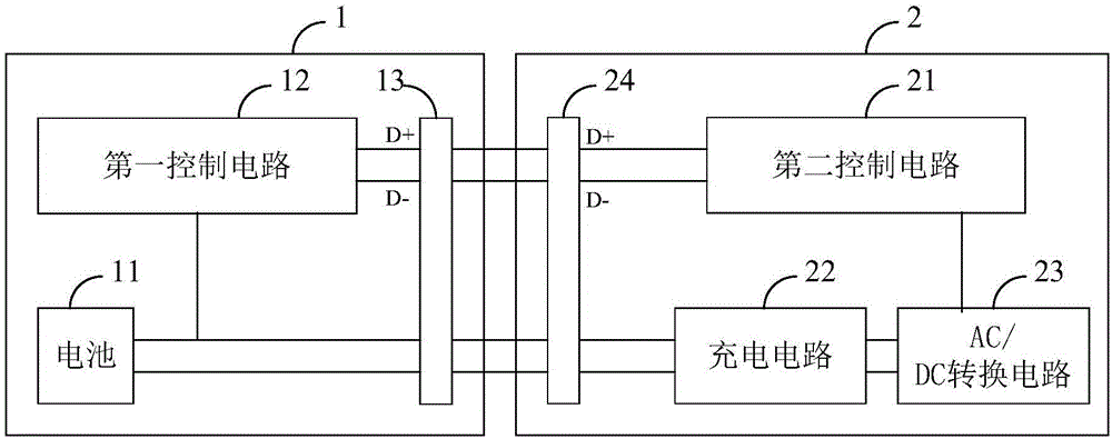
[0024] See figure 1 as shown, figure 1 is a schematic structural diagram of the charging system according to the first embodiment of the present invention. like figure 1 As shown, the charging system disclosed in this embodiment includes: a mobile terminal 1 and a charger 2 , and the charger 2 is used to charge the battery 11 of the mobile terminal 1 .

[0025] The mobile terminal 1 includes a first control circuit 12 , a battery 11 and a fi...


PUM


Abstract

The invention discloses a charging system, which comprises a mobile terminal and a charger, wherein the charger is used for charging a battery of the mobile terminal; the mobile terminal comprises a first control circuit; the charger comprises a second control circuit and a charging circuit; the first control circuit is coupled to the second control circuit; the charging circuit is coupled to the battery; and when the first control circuit and the second control circuit establish handshake communication, the charging circuit charges the battery. In the manner, the charging circuit is arranged on the charger, so that the problem of temperature rise of the mobile terminal can be solved.

Description

technical field [0001] The invention relates to the technical field of charging, in particular to a charging system. Background technique [0002] Currently, the charging circuit of a mobile terminal (such as a mobile phone) is set on the mobile terminal. like figure 1 As shown, the charging system of the mobile terminal in the prior art includes: a charger 11 and a mobile terminal 12 , and the mobile terminal 12 includes a charging circuit 121 , a power management chip 122 and a battery 123 . The power management chip 122 is respectively connected to the charging circuit 121 and the battery 123 for controlling the charging current of the charging circuit 121 according to the power of the battery 123 , and the charger 11 is connected to the charging circuit 121 . [0003] When the mobile terminal 12 is charging, the charging circuit 121 causes the mobile terminal 12 to generate heat due to power consumption. Contents of the invention [0004] An embodiment of the presen...

Claims


Application Information

Patent Timeline
IPC IPC(8): H02J7/00H02J7/02
Inventor 王海瑞李新倪漫利王晨牛乔万
Owner SHENZHEN TINNO WIRELESS TECH
Why Eureka
Try Eureka