Radio frequency performance test device

A technology for testing equipment and radio frequency performance, applied in the field of electronics, can solve the problems of difficult to adjust placement, reduce shielding, inconvenient and flexible adjustment, etc., to achieve the effect of improving efficiency, fast and accurate adjustment, and facilitating signal transmission

Active Publication Date: 2015-11-25
GUANGDONG OPPO MOBILE TELECOMM CORP LTD
View PDF4 Cites 20 Cited by
  • Summary
  • Abstract
  • Description
  • Claims
  • Application Information

AI Technical Summary

Problems solved by technology

[0003] At present, the existing test methods mainly include the following two types: the first one is to use a coupling triangular cone shielding box to test the radio frequency performance of the antenna of the terminal by using signaling test equipment. UniversalSerialBus (USB) cable inlet can only be connected to the USB cable after modification, but the above method will reduce the shielding performance, thereby affecting the test results, and because the terminal position is fixed, it is not convenient to check the position of the tested object when testing in different frequency bands. Flexible adjustment
The second is to use a shielding box with a flat-panel antenna. For mobile phones with multiple antennas, it is difficult to adjust the placement of the device so that the accuracy of the test results is not high.

Method used


Image

  • Radio frequency performance test device
  • Radio frequency performance test device
  • Radio frequency performance test device

Examples


Embodiment Construction

[0021] The following will clearly and completely describe the technical solutions in the embodiments of the present invention with reference to the accompanying drawings in the embodiments of the present invention. Obviously, the described embodiments are some of the embodiments of the present invention, but not all of them. Based on the embodiments of the present invention, all other embodiments obtained by persons of ordinary skill in the art without making creative efforts belong to the protection scope of the present invention.

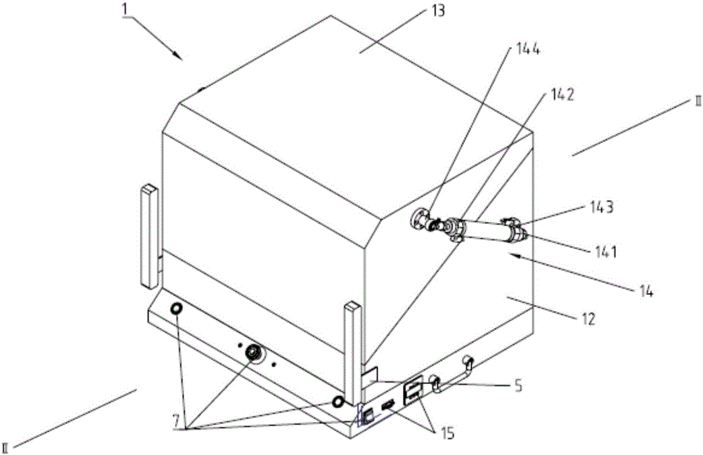
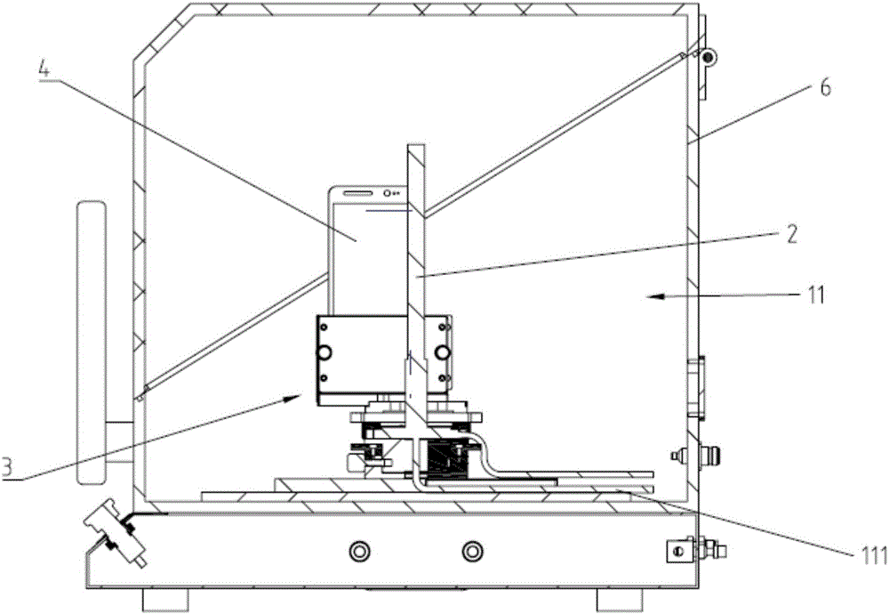
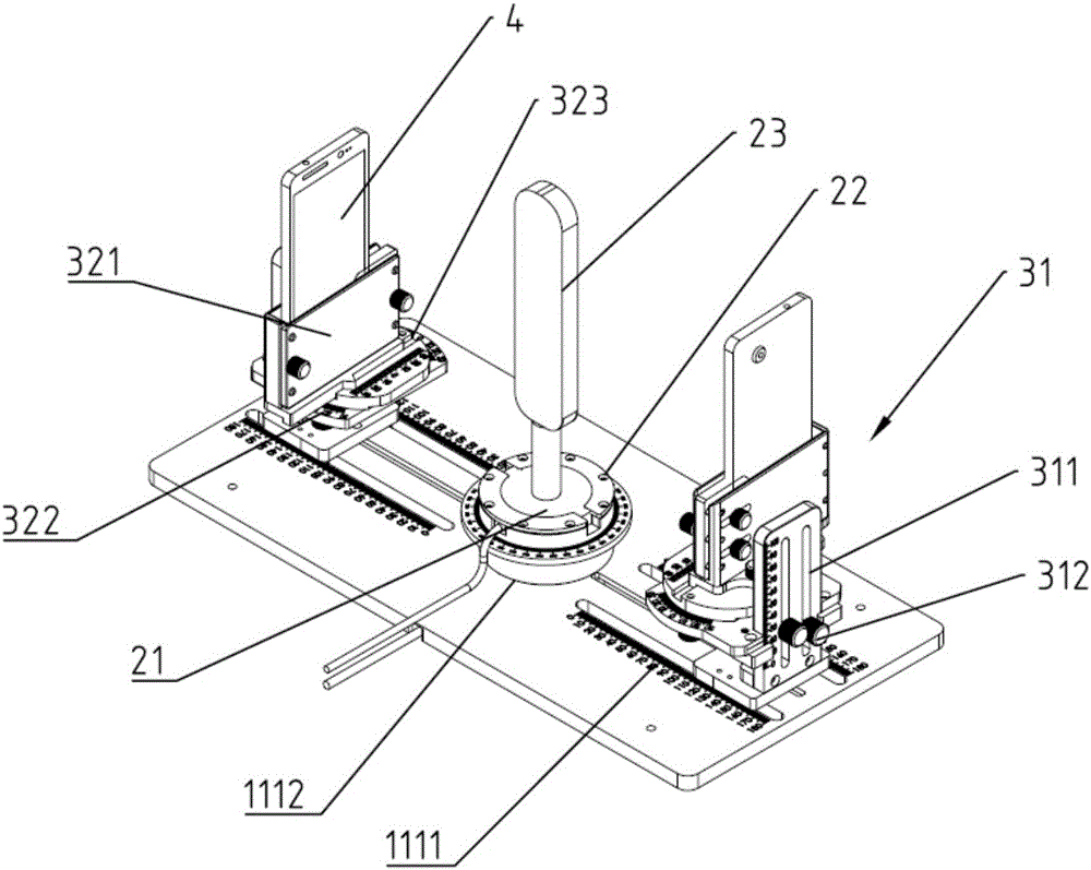
[0022] Please refer to Figure 1-3 , figure 1 It is a schematic diagram of a radio frequency performance testing device provided by an embodiment of the present invention. figure 2 Sectional view of the RF performance test device along part II-II. image 3 It is a schematic diagram of the internal structure of a radio frequency performance testing device, and the present invention provides a radio frequency performance testing device including:...


PUM


Abstract

The invention discloses a radio frequency performance test device comprising a shielding box, an antenna and a clamp. The shielding box comprises a shielding cavity which is internally provided with a fixing plate. The antenna is fixedly connected on the fixing plate. The length direction of the antenna is perpendicular to the fixing plate. The clamp comprises a support and a tray. The support is slidably connected on the fixing plate along a direction close to or away from the antenna. The tray is slidably connected on the support. The sliding direction of the tray is perpendicular to the fixing plate. The tray is used for installing terminal equipment. The antenna transmits a radio frequency signal to the terminal equipment. According to the radio frequency performance test device, the position of the terminal equipment relative to the antenna is rapidly and accurately adjusted by arrangement of the clamp capable of adjusting the position of the terminal equipment so that signal transmission is facilitated, and radio frequency performance test efficiency and test result accuracy can be enhanced.

Description

technical field [0001] The invention relates to the field of electronic technology, in particular to a radio frequency performance testing device. Background technique [0002] In the production process of the wireless terminal, in order to ensure the production quality of the product, it is often necessary to conduct an antenna coupling test, and then determine whether the antenna in the wireless terminal meets the performance requirements through the test. [0003] At present, the existing test methods mainly include the following two types: the first one is to use a coupling triangular cone shielding box to test the radio frequency performance of the antenna of the terminal by using signaling test equipment. UniversalSerialBus (USB) cable inlet can only be connected to the USB cable after modification, but the above method will reduce the shielding performance, thereby affecting the test results, and because the terminal position is fixed, it is not convenient to check th...

Claims


Application Information

Patent Timeline
Patent Type & Authority Applications(China)
IPC IPC(8): H04B17/12
Inventor 黄志勇王小海
Owner GUANGDONG OPPO MOBILE TELECOMM CORP LTD
Why Eureka
Try Eureka