Method, system and equipment for determining reference subframe
A technology for referring to subframes and subframes, which is applied in the field of wireless communication and can solve problems such as increased power consumption of equipment and increased processing complexity of user equipment.
- Summary
- Abstract
- Description
- Claims
- Application Information
AI Technical Summary
Problems solved by technology
Method used
Image
Examples
Embodiment 1
[0174] like figure 2 As shown, a method for determining a reference subframe in Embodiment 1 of the present invention includes the following steps:
[0175] Step 200, the user equipment determines at least two sets of downlink CSI measurement subframes configured by the network side;
[0176] Step 201: For a downlink CSI measurement subframe set, the user equipment determines the downlink A-CSI reference subframe sequence number of the downlink CSI measurement subframe set according to preset rules, and according to the determined downlink A-CSI reference subframe number, The CSI reference subframe number determines the downlink A-CSI reference subframe.
[0177] Among them, the preset rules include some or all of the following rules:
[0178] According to the downlink A-CSI reference subframe configured by the network side device for the user equipment, determine the subframe sequence number corresponding to the subset of the downlink CSI measurement subframe set as the do...
example 1
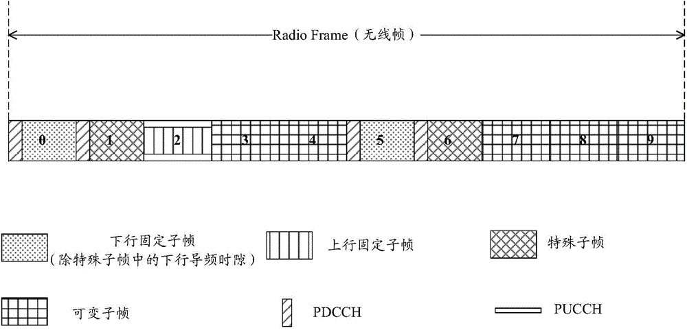
[0211] based on Figure 1F Based on the example above, if the network side configures subframe #4 in subframe set 2 as its A-CSI reference subframe, the user equipment needs to measure or store the signal of subframe #4 in radio frame L-1 in advance to prepare for possible The A-CSI of set 2 fed back in subframe #2 of radio frame L triggered by the A-CSI trigger signaling received in subframe #5 in radio frame L−1.
[0212] When subframe #4 in radio frame L-1 is uplink, the user equipment saves the advance measurement results or stored signals in the previous cycle, that is, when subframe #4 in radio frame L-2 is downlink (if radio frame L In -2, subframe #4 is still uplink, then find the advance measurement result or stored signal) when subframe #4 is downlink) for A-CSI reporting of possible subsequent set 2.
[0213] In subframe set 1, after the A-CSI trigger signaling subframe (including this subframe), the user equipment can always find a valid A-CSI reference subframe t...
example 2
[0215] like Figure 4 As shown, when the uplink reference configuration is UL-DL configuration#2, the A-CSI trigger signaling may be sent in subframes {3,8}, and the division method of the subframe set is: set1 contains {0,1,5 ,6}, set2 contains {3,4,7,8,9}.
[0216] The network side configures subframe #5 in set1 as the A-CSI reference subframe of the subframe set, then the user equipment only needs to measure and store the signal of subframe #5 in advance, so as to prepare for the signal that may be generated in subframe #8 or # 3 The A-CSI of the subframe set 1 that is respectively fed back in the subsequent subframe #2 or subframe #7 triggered by the received A-CSI triggering signaling.
[0217] In subframe set 2, the A-CSI reference resource subframe #8 or #3 determined according to the original scheme is always a downlink subframe (the downlink subframe in the uplink reference configuration cannot be dynamically changed to uplink), so the subframe set In 2, the user eq...
PUM
 Abstract
Description
Claims
Application Information
 - R&D
- Intellectual Property
- Life Sciences
- Materials
- Tech Scout
- Unparalleled Data Quality
- Higher Quality Content
- 60% Fewer Hallucinations
Browse by: Latest US Patents, China's latest patents, Technical Efficacy Thesaurus, Application Domain, Technology Topic, Popular Technical Reports.
© 2025 PatSnap. All rights reserved.Legal|Privacy policy|Modern Slavery Act Transparency Statement|Sitemap|About US| Contact US: help@patsnap.com


