Laser radar system, laser radar point cloud data processing method and readable medium

A laser radar and laser transceiver technology, applied in the field of automatic identification, to achieve low system processing complexity, reduce processing complexity, and low cost effects

Inactive Publication Date: 2018-07-10
HESAI TECH CO LTD
View PDF1 Cites 27 Cited by
  • Summary
  • Abstract
  • Description
  • Claims
  • Application Information

AI Technical Summary

Problems solved by technology

[0005] The technical problem solved by the embodiments of the present invention is how to improve the angular resolution of laser radar with lower cost and lower system processing complexity

Method used


Image

  • Laser radar system, laser radar point cloud data processing method and readable medium
  • Laser radar system, laser radar point cloud data processing method and readable medium
  • Laser radar system, laser radar point cloud data processing method and readable medium

Examples


Embodiment Construction

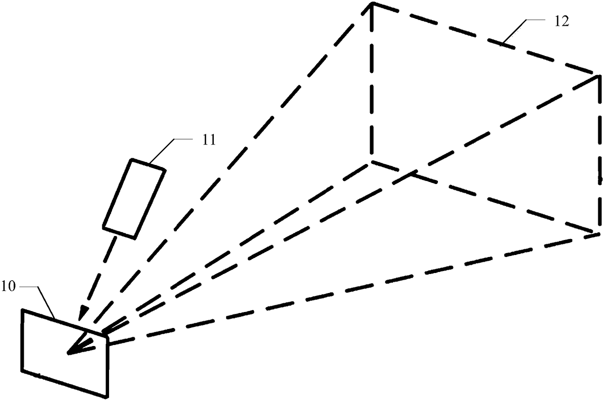
[0023] Existing lidar systems such as figure 1 shown.

[0024] see figure 1 , the existing laser radar system includes: a scanning module 10 and a laser transceiver module 11, wherein the scanning module 10 is adapted to reflect the laser pulse signal emitted by the laser transceiver module 11 to space and receive space obstacles The reflected laser pulse echo signal is then reflected to the laser transceiver module 11 to realize the measurement of the spatial coordinates. The two-dimensional space corresponding to the echo signal detectable by the laser transceiver module 11 is the field of view 12 of the laser radar system.

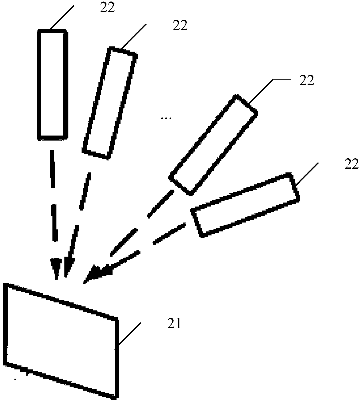
[0025] In the existing lidar, in order to improve the angular resolution, the logarithm of the transceiver module can only be doubled. Increasing the logarithm of the transceiver module not only leads to a sharp increase in cost, but also increases the volume and complexity of the system to a large extent, thus reducing the reliability of the system....


PUM


Abstract

The invention relates to a laser radar system, a laser radar point cloud data processing method and a readable medium. The laser radar system comprises a scanning module and a plurality of laser transmitting and receiving modules; the scanning module is suitable for reflecting laser pulse signals into a space, and receiving laser pulse echo signals reflected by a space obstacle; each laser transmitting and receiving module emits laser to the scanning module with a preset angle corresponding to the laser transmitting and receiving module; and fields of view corresponding to at least two laser transmitting and receiving modules have an overlapping region. With the above laser radar system adopted, the angular resolution of a laser radar can be improved at a lower cost and with lower system processing complexity.

Description

technical field [0001] Embodiments of the present invention relate to the field of automatic identification, and in particular, relate to a laser radar system, a processing method for laser radar point cloud data, and a readable medium. Background technique [0002] Because it can detect the three-dimensional coordinate model of the target around the vehicle body to achieve the purpose of environmental perception, the lidar system is widely used in various fields such as automatic driving. L4 and above unmanned driving systems require vehicle-mounted lidar to have a larger detection field of view, longer range, and higher angular resolution. For example, lidar is required to be 100-200 meters or farther away At a distance, it can accurately identify targets such as cars and pedestrians. [0003] Existing lidar can detect and identify targets at relatively short distances. Due to insufficient resolution at long distances, the number of points on the actual point cloud image ...

Claims


Application Information

Patent Timeline
Patent Type & Authority Applications(China)
IPC IPC(8): G01S17/02G01S7/48
CPCG01S17/02G01S7/48
Inventor 向少卿叶良琛王瑞朱雪洲李一帆
Owner HESAI TECH CO LTD
Why Eureka
Try Eureka