Supercharge Your Innovation With Domain-Expert AI Agents!

Circuit breaker

A circuit breaker and circuit technology, applied in circuits, circuit breaker parts, electrical switches, etc., can solve the problem of the overall size of circuit breakers, and achieve the effects of realizing device cost, realizing miniaturization, and preventing dust from entering.

Active Publication Date: 2015-11-25
FUJI ELECTRIC FA COMPONENTS & SYST CO LTD
View PDF6 Cites 0 Cited by
  • Summary
  • Abstract
  • Description
  • Claims
  • Application Information

AI Technical Summary

Problems solved by technology

However, it is difficult to make the base portion 8a of the operating handle 8 large due to the arrangement space of other circuit breaker components, and the entire circuit breaker may become large.

Method used


Image

  • Circuit breaker
  • Circuit breaker
  • Circuit breaker

Examples


Embodiment Construction

[0033] Hereinafter, modes for implementing the present invention (hereinafter referred to as embodiments) will be described in detail with reference to the drawings.

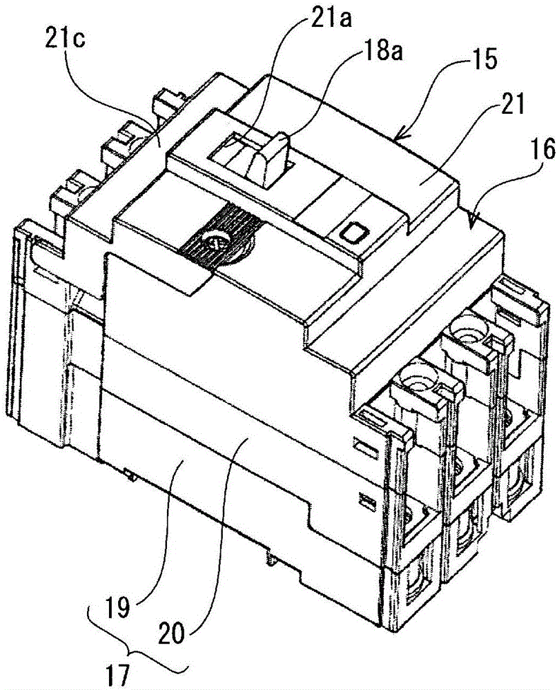
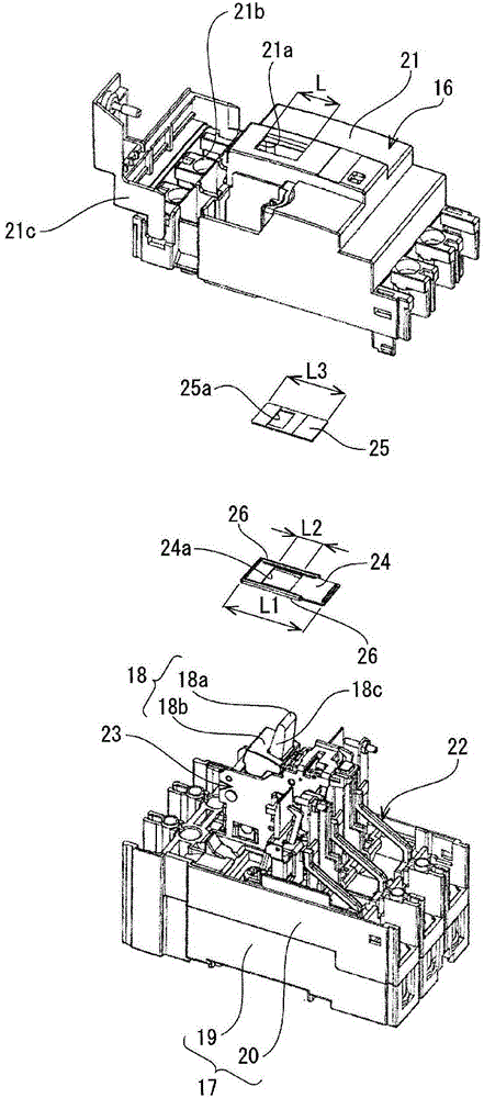
[0034] figure 1 is a perspective view showing the appearance of the circuit breaker 15 of the present invention, figure 2 It is an exploded perspective view of the circuit breaker 15 .

[0035] Such as figure 1 As shown, the circuit breaker 15 of the present embodiment has a cover 16 and a case 17 formed by resin molding, and the handle 18 a of the operating handle 18 described later is a rectangular shape formed by opening from the upper surface of the cover 16 . The handle window frame 21a protrudes outward.

[0036] The housing 17 is composed of a lower housing 19 forming the bottom of the circuit breaker 15 and an intermediate housing 20 attached to the upper portion of the lower housing 19 .

[0037] The cover 16 is attached to the upper portion of the intermediate case 20, and is composed of an uppe...


PUM


Abstract

The present invention is provided with a first shutter (24) and a second shutter (25). The first shutter (24) has an insertion hole (24a) formed between a base section (18b) of an operation handle (18) and a handle opening frame (21a) formed on a cover (21), the insertion hole (24a) being disposed on the base section (18b). A gripped part (18a) inserts into the insertion hole (24a). The second shutter (25) moves in association with the gripped part (18a). At the on and off positions of the operation handle, the first shutter (24) is extended from the front and back edges of the handle opening frame in the longitudinal direction so as to shut the handle opening frame, and the second shutter is extended from the front and back ends of the insertion hole (24a) in the longitudinal direction so as to shut the insertion hole.

Description

technical field [0001] The present invention relates to a circuit breaker aimed at a circuit breaker for wiring, a circuit breaker, etc., and specifically relates to a structure for preventing dust from entering through a handle window frame provided in a main body case. Background technique [0002] Figure 7 It is figure showing conventional circuit breaker. 1 is a case made of molded resin, and 2 is a cover made of molded resin. The case 1 accommodates the power supply side terminal board 3, the second moving contact 4, the first moving contact 5, and the arc extinguishing chamber 6. , Switch mechanism 7, operating handle 8, overcurrent release device 9, load side terminal board 10, etc. [0003] The operating handle 8 is a resin molded product in a shape in which the knob portion 8b rises upward from the center of the brim-shaped base portion 8a having a circular arc cross section. The handle portion 8b protruding outward through the handle window frame 2a opened in th...

Claims


Application Information

Patent Timeline
Patent Type & Authority Applications(China)
IPC IPC(8): H01H73/06H01H73/02H01H73/12
CPCH01H71/04H01H9/04H01H2071/046H01H9/16H01H21/08H01H21/22
Inventor 广瀬高峰浜田佳伸细冈洋平
Owner FUJI ELECTRIC FA COMPONENTS & SYST CO LTD
Features
  • R&D
  • Intellectual Property
  • Life Sciences
  • Materials
  • Tech Scout
  • Unparalleled Data Quality
  • Higher Quality Content
  • 60% Fewer Hallucinations
Learn More