Antenna device and electronic equipment

An antenna device and electronic equipment technology, which is applied to antenna supports/installation devices, antennas, antenna parts, etc., can solve the problem of frequent use of antenna modules, and achieve the effects of stable communication characteristics, efficient induction, and improved communication characteristics

Active Publication Date: 2015-11-25
DEXERIALS CORP
View PDF4 Cites 3 Cited by
  • Summary
  • Abstract
  • Description
  • Claims
  • Application Information

AI Technical Summary

Problems solved by technology

In addition, the antenna module used to realize the non-contact charging function has gradually become frequently used

Method used


Image

  • Antenna device and electronic equipment
  • Antenna device and electronic equipment
  • Antenna device and electronic equipment

Examples


Deformed example 1

[0063] The magnetic sheet 20 constituting the antenna device 1 does not need to cover the entire surface of the antenna coil 12. As long as it overlaps a part of the antenna coil 12, the magnetic flux concentrated at the end 3a of the metal foil 3 can be introduced, and an induced current can be generated in the antenna coil. That's it. Weight reduction and thinning can be improved by reducing the number of magnetic sheets 20 .

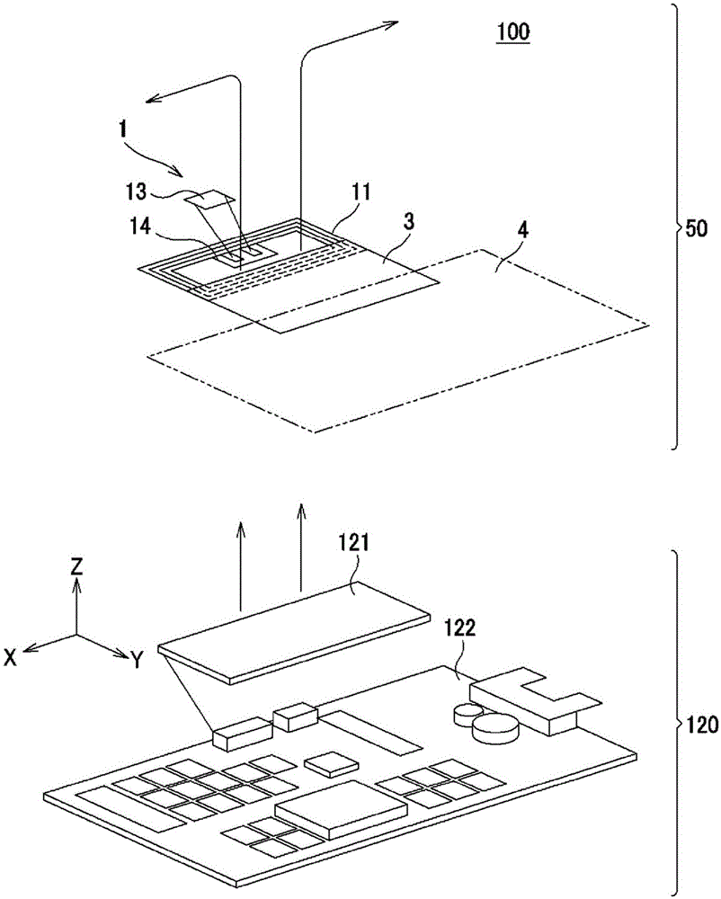
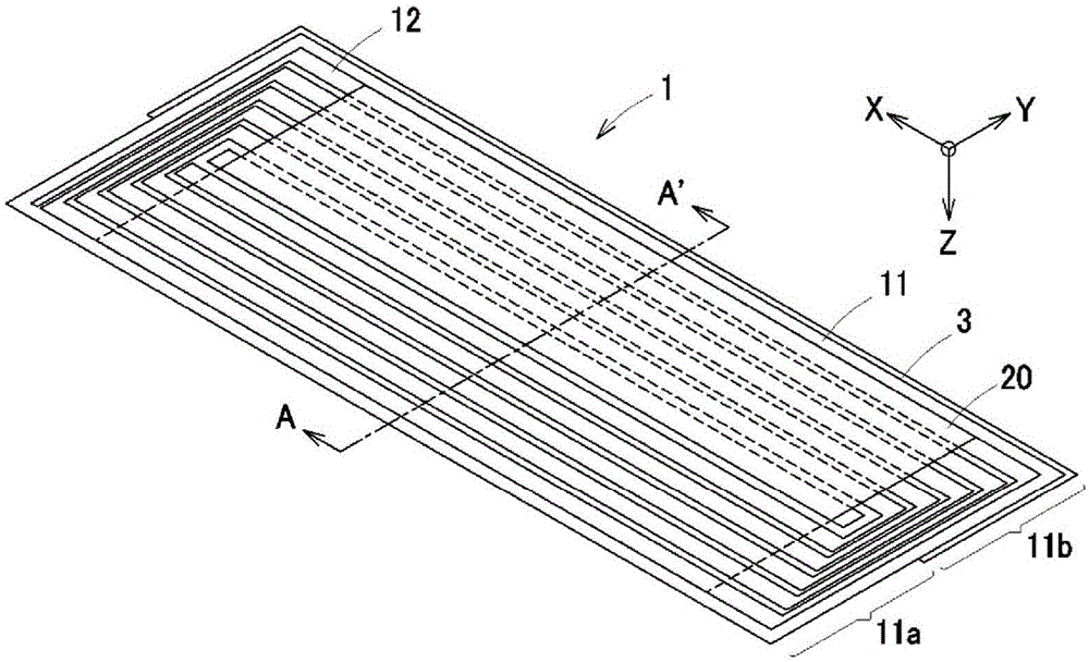
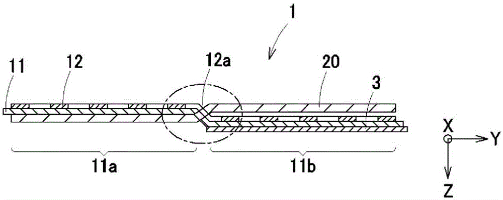
[0064] Such as Figure 4A and Figure 4B As shown, the antenna device 1 is provided with an antenna coil 12 assembled in the frame of the electronic device and communicating with an inductively coupled reader 120, an antenna substrate 11 on which the antenna coil 12 is mounted, and an antenna coil 12 generated by the antenna coil 12. The communication processing unit 13 driven by electric power. On the surface of the antenna substrate 11 opposite to the surface facing the reader / writer 120 , the metal foil 3 is arranged to overlap a part of the ant...

Deformed example 2

[0069] In the antenna device 1 , the metal foil 3 is formed to cover only the antenna coil 12 on the other side 11 b of the antenna substrate 11 . In general, since there are a plurality of metallic internal structures that shield magnetic flux inside the housing of electronic device 50, as long as these internal structures can be brought close to or overlapped with the metal foil 3, the magnetic flux can be shielded. What is necessary is just to introduce the magnetic flux concentrated at the end portion 3 a of the metal foil 3 to the magnetic sheet 20 by utilizing the path. This is merely to use the metal internal structure inside the housing as a path for guiding the magnetic flux, and is not limited to arranging the internal structure so that the path can be formed more efficiently. Therefore, the metal foil 3 constituting the antenna device 1 has a larger area to positively form a shielding path of magnetic flux.

[0070] Such as Figure 6A and Figure 6B As shown, in ...

Deformed example 3

[0075] The metal foil 3 may be formed on either surface of the antenna substrate 11 as long as it overlaps the other side 11 b of the antenna coil 12 .

[0076] Such as Figure 9A and Figure 9B As shown, the antenna device 1 b includes an antenna substrate 11 , an antenna coil 12 formed on one surface of the antenna substrate, and a metal foil 3 formed to overlap a part of the antenna coil 12 .

[0077] The antenna device 1b is also provided with a rectangular magnetic sheet 20 overlapping with the antenna coil 12. The magnetic sheet 20 is arranged on the side 11a of the antenna coil on the surface opposite to the surface facing the reader / writer 120. The other side 11b is arranged on the side facing the reader / writer 120 . In addition, the metal foil 3 is formed between the magnetic sheet 20 and the antenna substrate 11 on the other side of the antenna coil 12 . Even in such cases, such as Figure 9C As shown, the magnetic flux is concentrated in the vicinity of the end ...


PUM


Abstract

The present invention is provided with: an antenna substrate (11) on which an antenna coil (12) inductively coupled with a reader / writer (120) is looped; a metallic foil (3) which is provided to the antenna substrate (11) so that at least a part of the antenna coil (12) overlaps the same; and a magnetic sheet (20) which is arranged so as to overlap the antenna coil (12), and which draws magnetic fields into the antenna coil (12). At one side (11a) of the antenna coil (12), in which the current flowing in the conductive line of the antenna coil (12) circulates in one direction, the antenna coil (12) is closer to the reader / writer (120) than the magnetic sheet (20) is, and / or at the other side (11b) of the antenna coil (12), in which the current flowing in the conductive line of the antenna coil (12) circulates in the opposite direction, the magnetic sheet (20) is closer to the reader / writer (120) than the antenna coil (12) is. The metallic foil (3) only overlaps with said other side (11b) of the antenna coil (12).

Description

technical field [0001] The present invention relates to an antenna device incorporated in electronic equipment and communicating with external equipment using electromagnetic field signals, and electronic equipment incorporating the antenna device. This application claims priority on the basis of Japanese Patent Application No. Japanese Application No. 2013-056778 filed in Japan on March 19, 2013, and this application is referred to and incorporated in this application. Background technique [0002] Conventionally, electronic devices such as mobile phones, smartphones, and tablet PCs have been equipped with antenna modules for RFID (Radio Frequency Identification) because they are equipped with short-range non-contact communication functions. In addition, the antenna module used to realize the non-contact charging function is gradually becoming more and more frequently used. [0003] Such an antenna module communicates by inductive coupling with an antenna coil of a transmi...

Claims


Application Information

Patent Timeline
Patent Type & Authority Applications(China)
IPC IPC(8): H01Q7/06G06K17/00G06K19/07H01Q1/24
CPCH01Q7/06G06K19/07771H01Q1/38H01Q1/2208H01Q1/243
Inventor 折原勝久
Owner DEXERIALS CORP
Why Eureka
Try Eureka