Shaft type workpiece holder

A workpiece fixture and shaft workpiece technology, applied in the field of shaft workpiece fixtures, can solve the problems affecting workpiece machining accuracy, stable clamping of shaft workpieces, workpiece rotation, etc., and achieve the effect of high machining accuracy

Inactive Publication Date: 2015-12-02
NANTONG HENGDING HEAVY DUTY MACHINE TOOL
View PDF0 Cites 3 Cited by
  • Summary
  • Abstract
  • Description
  • Claims
  • Application Information

AI Technical Summary

Problems solved by technology

[0003] However, during the processing of shaft workpieces, due to the curved surface of the forming surface, traditional fixed chucks or fixtures cannot achieve stable clamping of shaft workpieces, resulting in unfastened clamping during processing. Rotation of the workpiece and other problems seriously affect the machining accuracy of the workpiece

Method used


Image

  • Shaft type workpiece holder
  • Shaft type workpiece holder
  • Shaft type workpiece holder

Examples


Embodiment Construction

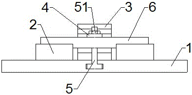
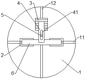
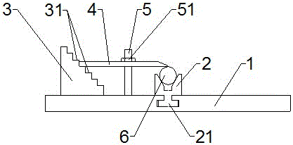
[0015] like figure 1 , figure 2 and image 3 As shown in the figure, the present invention discloses a shaft workpiece fixture, which includes an installation disc 1, a positioning V-shaped block 2 and a clamping device arranged on the installation disc 1. The installation disc 1 is provided with two mutual The vertical guide groove A11 and the guide groove B12, the cross-section of the guide groove A11 and the guide groove B12 are inverted T-shaped.

[0016] The positioning V-shaped blocks 2 are a pair, which are symmetrically arranged on the installation disk 1 along the extending direction of the guide groove A11, and the center lines of the two positioning V-shaped blocks 2 coincide with the center line of the guide groove A11; the lower end of the positioning V-shaped block 2 There is a slider A21 matched with the guide groove A11 and slidably matched with the mounting disc 1 .

[0017] The clamping device is arranged on the installation disk 1, and its center line co...


PUM


Abstract

The invention relates to a shaft type workpiece holder used for clamping of a shaft type workpiece. The shaft type workpiece holder comprises a mounting disc, and positioning V-shaped blocks and a holding device that are arranged on the mounting disc, wherein the mounting disc is provided with a guide groove A and a guide groove B along the diameter direction of the mounting disc; the guide groove A and the guide groove B are mutually perpendicular; the cross sections of the guide groove A and the guide groove B are inverted-T-shaped; the number of the positioning V-shaped blocks is two; the positioning V-shaped blocks are symmetrically arranged on the mounting disc along the extension direction of the guide groove A; center lines of the two positioning V-shaped blocks are coincided with that of the guide groove A; the holding device is arranged on the mounting disc; the center line of the holding device is coincided with the center line of the guide groove B; and the holding device comprises a supporting block, a pressure plate and a locking bolt. The shaft type workpiece holder has the advantages that the shaft type workpiece is positioned by the two positioning V-shaped blocks, and is held by the holding device, thereby realizing the clamping of the shaft type workpiece; the clamping is more secure; the possibility of rotation is low; and the machining precision is higher.

Description

technical field [0001] The invention relates to a workpiece fixture, in particular to a shaft workpiece fixture. Background technique [0002] In the process of workpiece processing, the workpiece needs to be clamped and fixed to ensure the stability of the workpiece during processing and to improve the machining accuracy of the workpiece. Generally, there are various fixed chucks or fixed fixtures in the workpiece processing. [0003] In the processing of shaft workpieces, due to the curved surface of the forming surface, the traditional fixed chuck or fixed fixture cannot achieve stable clamping of the shaft workpiece, resulting in the lack of tightening of the clamping during the processing. The workpiece rotation and other problems seriously affect the machining accuracy of the workpiece. SUMMARY OF THE INVENTION [0004] The technical problem to be solved by the present invention is to provide a clamp which is suitable for clamping and fixing shaft workpieces and has...

Claims


Application Information

Patent Timeline
Patent Type & Authority Applications(China)
IPC IPC(8): B25B11/00
CPCB25B11/00
Inventor 刘广晶
Owner NANTONG HENGDING HEAVY DUTY MACHINE TOOL
Why Eureka
Try Eureka