Modularized rotational-flow air-flotation filtering device

A swirling air flotation and filtration device technology, which is applied in chemical instruments and methods, flotation water/sewage treatment, centrifugal separation water/sewage treatment, etc., can solve problems such as hindering the formation of swirling fluid, easy formation of bias flow, and pressure reduction

Inactive Publication Date: 2015-12-02
JIANGSU HUADA ENVIRONMENTAL ENG CO LTD
View PDF4 Cites 8 Cited by
  • Summary
  • Abstract
  • Description
  • Claims
  • Application Information

AI Technical Summary

Problems solved by technology

The cavity formed by the cyclone cylinder and the tank body mentioned in this patent is similar to an inverted funnel, the lower part is wide and the upper part is narrow, and the sewage enters from the lower part. This structure cannot form an effective swirling fluid; the connection between the cone and the cylinder is sharp. , which greatly affects the swirl flow; eventually resulting in poor swirl separation effect
When the dissolved air water enters the wide bottom of the cyclone cylinder from the inlet pipe, the pressure drops instantly, and a large number of microbubbles released will hinder the formation of the swirl fluid in the wide lower part and narrow upper part, and the unstable swirl structure It also greatly affects the effect of dissolved air release
The setting method of the oil collection tank is likely to cause a high water content in the discharged dirty oil
The filter unit proposed in this patent adopts a large-resistance water distribution method, which is not conducive to uniform backwashing and is easy to form a biased flow; the upper part of the filter bed mentioned in this patent uses a filter to block the filter material, corresponding to fine-grained quartz sand and anthracite, etc. This method is basically The blocking effect cannot be realized, and the backwash expansion space is limited, and a large amount of material running out during backwash operation is inevitable
The matching nozzles and instruments of this patent are many, the operation is complicated, the failure rate is high, and the practicability is not strong

Method used


Image

  • Modularized rotational-flow air-flotation filtering device

Examples


Embodiment 1

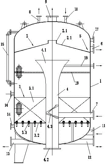
[0021] Embodiment 1: a modular cyclone air flotation filter device, comprising a cylinder 1, in which a slag collection tank 2 and a filter material layer 3 are arranged at intervals from top to bottom in the cylinder 1, and a cyclone is arranged in the center of the cylinder 1 4. The cyclone 4 is a cylindrical pipe body, the nozzle 4.1 at the upper end of the pipe body is directly below the slag collection tank 2, and the nozzle at the lower end protrudes from the lower head of the cylinder 1 as the sewage outlet 4.2, and the slag collection tank 2 is composed of a conical cylinder 2.1 with an inverted V-shaped cross section and a vertically upward scum pipe 2.2 set in the center of the conical cylinder 2.1. The side wall is sealed and connected, the upper surface of the wall of the slag collection tank 2 conical cylinder 2.1 and the cylinder wall of the cylinder 1 form a slag collection area 5, and the slag discharge port 6 begins to be formed on the side wall of the cylinder...

Embodiment 2

[0022] Embodiment 2: Referring to Embodiment 1, a swirl deflector 4.3 is arranged in the body of the cyclone 4, and the swirl deflector 4.3 is spirally inclined upward at an angle of 10-15°. The nozzle 4.1 at the upper end of the cyclone 4 pipe body is set as a bell mouth with a rising parabola outward.

Embodiment 3

[0023] Embodiment 3: with reference to embodiment 1 or 2, filter material intercepting net 19 is provided with above filter material layer 3.

[0024] The pressurized sewage is lifted by the pump and passes through the static mixer outside the device to mix the coagulant and flocculant, then merges into the dissolved air water, enters the cyclone in the tangential direction through the water inlet pipe 7, enters the cyclone 4, and passes through the cyclone diversion Plate 4.3 moves upward in a spiral separation process. During the spiral separation process, the sediment slides down along the inner wall of the cyclone and enters the sewage outlet. Then, the sludge discharge valve is automatically controlled by the PLC program according to the calculation of the amount of sludge entering the water for regular sludge discharge.

[0025] The rising dissolved air sewage condenses and coagulates the scum (oil) at the diffusion port on the upper part of the cyclone 4 by compressing t...


PUM

PropertyMeasurementUnit
particle diameteraaaaaaaaaa

Abstract

The invention discloses a modularized rotational-flow air-flotation filtering device which is suitable for the field of industrial sewage purification treatment and special situation emergency treatment. The modularized rotational-flow air-flotation filtering device comprises a drum. A dross collecting trough and a filtering material layer are sequentially arranged in the drum in a spaced mode from top to bottom. A swirler is arranged in the center of the drum and is a cylindrical tube. A tube opening in the upper end of the tube directly faces the portion below the dross collecting trough, and a tube opening in the lower end of the tube extends out of a lower end socket of the drum to serve as a sewage outlet. The dross collecting trough is composed of a conical cylinder with the inverse-V-shaped cross section and a vertically-upward dross tube arranged in the center of the conical cylinder. The tail end of the cylinder wall of the conical cylinder of the dross collecting trough is connected with the side wall of the cylinder in a sealed mode. A dross collecting area is formed by the upper surface of the cylinder wall of the conical cylinder of the dross collecting trough and the cylinder wall of the cylinder. A dross outlet is formed in the portion, in the dross collecting area, of the side wall of the cylinder. A water inlet tube is tangentially connected with the tube wall of the lower middle of the swirler. As rotational-flow sediment, oil (dross) air flotation and filtering separating are integrated, and novel comet filter materials are adopted, the treatment load is increased, and the device area is reduced.

Description

technical field [0001] The invention belongs to the field of industrial sewage purification treatment, especially relates to the separation of sediment, oil and suspended matter in sewage, and adopts automatic sewage treatment equipment for cyclone separation, air flotation separation and filtration separation, specifically an automatic sewage treatment equipment for Modular three-phase separation device for sludge and oily wastewater treatment. Background technique [0002] With the strengthening of people's awareness of environmental protection, higher requirements have been placed on the impact of wastewater discharged from industrial and mining enterprises on the surrounding environment. For example, oilfield wastewater containing a large amount of suspended solids, oil and sediment, traditional treatment Methods include sedimentation, air flotation, etc., but they all have their limitations, and are affected by many factors such as pollutant composition in wastewater, w...

Claims


Application Information

Patent Timeline
Patent Type & Authority Applications(China)
IPC IPC(8): C02F1/24C02F1/38C02F1/00
Inventor 万斌叶永东
Owner JIANGSU HUADA ENVIRONMENTAL ENG CO LTD
Why Eureka
Try Eureka