Rotary brick laying machine

A technology of a brick laying machine and a rotating device, applied in the field of construction machinery, can solve the problems of not being able to reserve a tree planting pit, reducing the adaptability of the brick laying machine, and poor movement of the turning crawler.

Active Publication Date: 2015-12-02
桑胜军
View PDF9 Cites 29 Cited by
  • Summary
  • Abstract
  • Description
  • Claims
  • Application Information

AI Technical Summary

Problems solved by technology

[0002] Floor tiles are laid on the ground of urban sidewalks, residential areas, garden squares and other places. The current construction methods are manual operations from leveling the ground, paving concrete cushions to laying floor tiles. The production efficiency is low and the construction quality is not good. ensure
[0003] At present, there have been floor tile laying machines, such as Chinese patents ZL201120178066.1 and ZL201320240578.5. This type of laying machine has realized the mechanization of floor tile laying and greatly improved the efficiency and quality of floor tile laying. However, during the construction process, it was found that This type of brick laying machine has the following deficiencies. First, it mainly depends on the poor movement of the crawler belt when turning. The ground cannot be used; the third is that the space such as the tree planting pit cannot be reserved, which reduces the adaptability of the brick laying machine

Method used


Image

  • Rotary brick laying machine
  • Rotary brick laying machine
  • Rotary brick laying machine

Examples


Embodiment 1

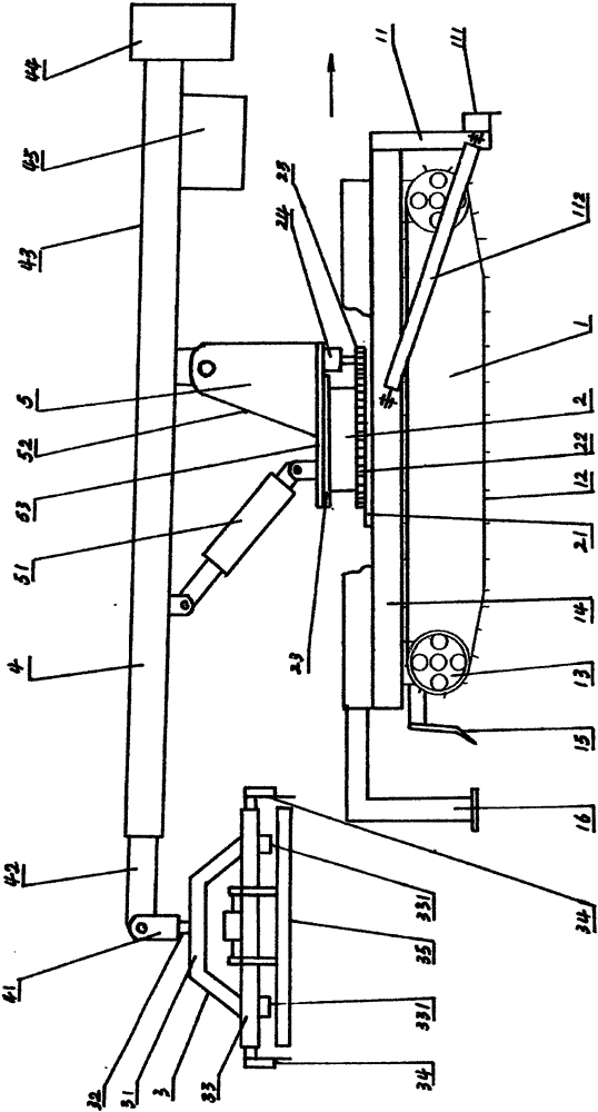
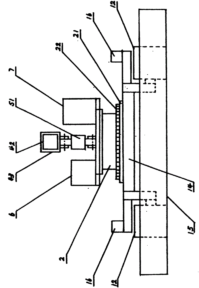
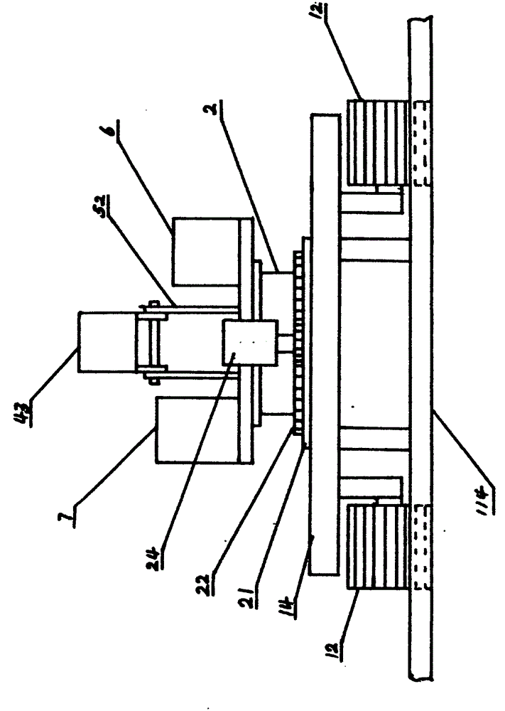
[0019] A rotary brick laying machine, mainly composed of a traveling device (1), a rotating device (2), a brick gripper (3), a suspension device (4), and a supporting device (5). The front end of the traveling device (1) is equipped with Shoveling device (11), main shoveling plate (114) in the middle of shoveling device (11), both sides are right shoveling flat plate (111) and left shoveling flat plate (115), left shoveling flat plate (115) and right shoveling flat plate ( 111) is connected with the main shovel plate (114) through the hinge hinge (113), the left shovel plate (115) and the right shovel plate (111) are connected with the chassis frame (14) through the diagonal brace (112), when not needed, The left shovel plate (115) or the right shovel plate (111) can be folded backward, the screed plate (15) is installed on the rear end of the walking device (1), and the chassis frame (14) is equipped with stabilizing brackets (16) on both sides, stable The support (16) can be...


PUM


Abstract

The invention discloses a rotary brick laying machine. The rotary brick laying machine is mainly composed of a travelling device, a rotation device, a brick clamp, a suspension device and a support device, wherein a shovelling device is arranged at the front end of the travelling device, and a levelling plate is arranged at the rear end of the travelling device; the rotation device is arranged at the middle part above a chassis frame, a fixed disc at the lower end of the rotation device is fixedly connected with the chassis frame, the support device is arranged above a rotation sleeve disc of the rotation device, a support chassis is fixedly connected with the rotation sleeve disc, a support oil cylinder and a support arm are installed on the support chassis, and the suspension device is installed at the upper end of the support arm and the upper end of the support oil cylinder; and the brick clamp is arranged below a telescopic arm of the suspension device. The rotary brick laying machine disclosed by the invention is capable of flexibly laying floor bricks on a fan-shaped laying surface, and adaptive to lay floor bricks on curve road surfaces, large-radian road surfaces or floors, road surfaces and floors with dead angles, and other complex road surfaces and floors.

Description

technical field [0001] The invention relates to the field of construction machinery, in particular to a rotary brick laying machine. Background technique [0002] Floor tiles are laid on the ground of urban sidewalks, residential areas, garden squares and other places. The current construction methods are manual operations from leveling the ground, paving concrete cushions to laying floor tiles, which has low production efficiency and poor construction quality. ensure. [0003] At present, there have been floor tile laying machines, such as Chinese patents ZL201120178066.1 and ZL201320240578.5. This type of laying machine has realized the mechanization of floor tile laying and greatly improved the efficiency and quality of floor tile laying. However, during the construction process, it was found that This type of brick laying machine has the following deficiencies. First, it mainly depends on the poor movement of the crawler belt when turning. The ground cannot be used; th...

Claims


Application Information

Patent Timeline
Patent Type & Authority Applications(China)
IPC IPC(8): E01C19/52
Inventor 桑胜军
Owner 桑胜军
Why Eureka
Try Eureka