Stable drill pipe

A technology for stabilizing drill pipes and stabilizing blocks, which is applied in the direction of drill pipes, drill pipes, drilling equipment, etc., and can solve problems such as jamming of stable drill pipes, drilling, drilling accidents, etc., and achieve the effect of prolonging the service life

Inactive Publication Date: 2015-12-02
BEIJING CHINA COAL MINE ENG CO LTD
View PDF5 Cites 0 Cited by
  • Summary
  • Abstract
  • Description
  • Claims
  • Application Information

AI Technical Summary

Problems solved by technology

For common straight-foil stabilized drill pipes, helical stabilized drill pipes and roller-type stabilized drill pipes (their stabilizing effect is similar to that of straight-flap stabilized drill pipes), under the rotation of straight-flap stabilized drill pipes, The mud carries rock slag upward in a spiral manner, and the rock slag is easily squeezed in the gap between the outer side of the stable drill pipe and the well wall during the rising process of the rock slag, resulting in faster wear of the wing plate, and even crushing the stable drill pipe. Cause drilling accidents, and the traditional helical stabilized drill pipe must match the rising speed of the rock slag between the spiral wings and the rotation speed of the drilling tool, so that the rock slag can rise in a straight line in the annular space, but the drilling geological conditions are bad, and the speed varies The geological conditions will change at any time. During the drilling process, the rock slag rising is only improved compared with the straight wing plate, but it is still easy to squeeze the stable drill pipe and cause drilling accidents.
When there is a sudden fluid leakage in the wellbore, the slag in the mud can easily cause sticking and drilling accidents at the helically stabilized drill pipe

Method used


Image

  • Stable drill pipe
  • Stable drill pipe

Examples


Embodiment Construction

[0021] In order to clearly illustrate the solutions in the present invention, preferred embodiments are given below and detailed descriptions are given in conjunction with the accompanying drawings.

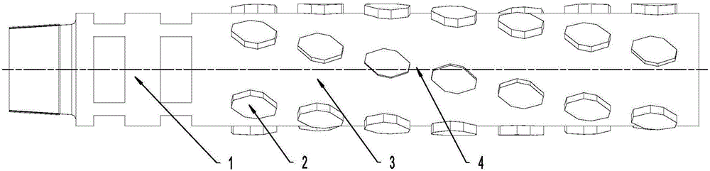
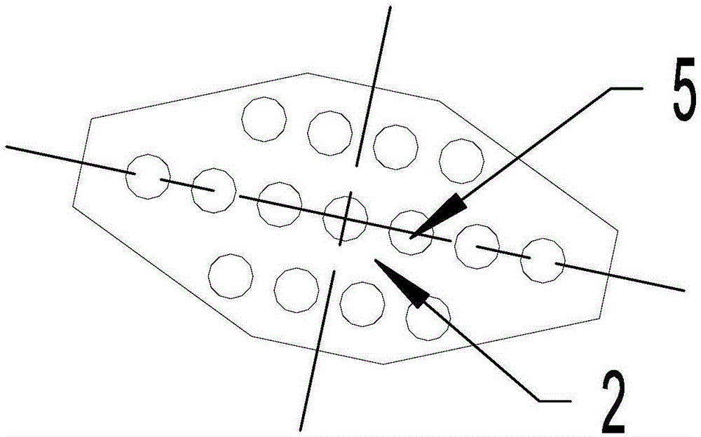
[0022] Such as figure 1 and figure 2 As shown, the stabilized drill pipe in this embodiment includes a rod body 1 and a stabilizing block 2 fixedly installed on the outer cylindrical surface of the rod body 1 , and a discharge channel is arranged between two adjacent stabilizing blocks 2 .

[0023] The stabilizing block 2 in this embodiment is an octagonal arc plate, and after the octagonal arc plate is unfolded, it is like a rugby ball with two small ends and a large middle, and the eight sides of the octagon arc plate are respectively The first side, the second side, the third side, the fourth side, the fifth side, the sixth side, the seventh side and the eighth side, the first side, the second side, the third side, The end of the fourth side, the fifth side, the sixth side,...


PUM


Abstract

The invention discloses a stable drill pipe. The stable drill pipe comprises a pipe body and stabilization blocks fixedly installed on the outer cylindrical face of the pipe body. A discharging channel is formed between every two adjacent stabilization blocks. The stabilization blocks are polygonal arc-shaped plates. On the outer cylindrical surface of the pipe body, the inner arc faces of the polygonal arc-shaped plates are fixedly connected with the outer cylindrical surface of the pipe body. The stable drill pipe is suitable for different rotation speeds under different geological conditions and can guarantee that rock residues can be smoothly carried to the ground in flushing fluid and avoid that when slurry leaks suddenly in a shaft, a wedging accident occurs.

Description

technical field [0001] The invention relates to the field of mining engineering machinery, in particular to a stable drill rod. Background technique [0002] In the process of full-bore drilling such as raising the pilot hole, the flushing fluid will carry the broken slag up to the ground from the gap between the flanges of the stabilizing drill pipe, and in this process, the stabilizing drill pipe will support the hole wall The effectiveness of the BHA is the key factor for the effectiveness of the bottom hole assembly, and it is one of the direct factors affecting the deviation of the borehole. For common straight-foil stabilized drill pipes, helical stabilized drill pipes and roller-type stabilized drill pipes (their stabilizing effect is similar to that of straight-flap stabilized drill pipes), under the rotation of straight-flap stabilized drill pipes, The mud carries rock slag in a spiral upward direction, and the rock slag is easily squeezed in the gap between the ou...

Claims


Application Information

Patent Timeline
Patent Type & Authority Applications(China)
IPC IPC(8): E21B17/00
Inventor 荆国业刘志强李恩涛程守业谭昊姜浩亮韩云龙张广宇李丙乾李俊峰于见水
Owner BEIJING CHINA COAL MINE ENG CO LTD
Why Eureka
Try Eureka