Head shaking drive mechanism, fan head shaking mechanism and fan

A driving mechanism and fan shaking head technology, which is applied in the direction of machines/engines, liquid fuel engines, mechanical equipment, etc., can solve the problems of increasing materials, increasing assembly time, and large space occupied by synchronous motors, so as to reduce costs and avoid occupying space oversized effect

Active Publication Date: 2015-12-02
格力大松(宿迁)生活电器有限公司 +1
View PDF9 Cites 2 Cited by
  • Summary
  • Abstract
  • Description
  • Claims
  • Application Information

AI Technical Summary

Problems solved by technology

[0004] However, the cost of using the synchronous motor to turn on and off the fan head is high, and the synchronous motor takes up a lot of space. It is necessary to increase the fixing bracket of the synchronous motor. While increasing the mater

Method used


Image

  • Head shaking drive mechanism, fan head shaking mechanism and fan
  • Head shaking drive mechanism, fan head shaking mechanism and fan
  • Head shaking drive mechanism, fan head shaking mechanism and fan

Examples


Embodiment Construction

[0030] The core of the present invention is to provide an oscillating head drive mechanism to avoid excessive space occupation and reduce costs while satisfying automatic control;

[0031] Another core of the present invention is to provide a fan oscillating mechanism and a fan.

[0032] Hereinafter, an embodiment will be described with reference to the drawings. In addition, the examples shown below do not limit the content of the invention described in the claims in any way. In addition, all the contents of the configurations shown in the following embodiments are not limited to be essential to the solution of the invention described in the claims.

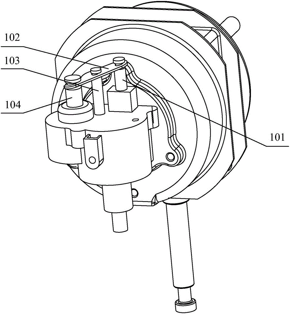
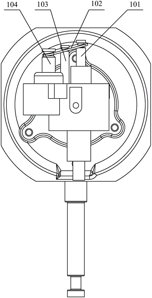
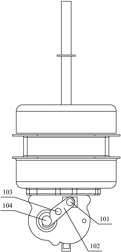
[0033] see Figure 1-Figure 3 , figure 1 Schematic diagram of the structure of the fan oscillating mechanism provided by the embodiment of the present invention; figure 2 The rear view of the fan oscillating mechanism provided by the embodiment of the present invention; image 3 It is a top view of the fan oscillating mech...


PUM


Abstract

The embodiment of the invention discloses a head shaking drive mechanism which comprises a telescopic drive rod, a supporting rod and a connection transmission piece for being connected with an end tooth box pull rod of a fan head shaking mechanism. Both the telescopic drive rod and the supporting rod are connected with the connection transmission piece, so that when the telescopic drive rod stretches out and draws back, the connection transmission piece drives the end tooth box pull rod to move up and down. The head shaking drive mechanism is applied to a fan with the end tooth box, the fan is additionally provided with the telescopic drive rod, the supporting rod and the connection transmission piece, both the telescopic drive rod and the supporting rod are connected with the connection transmission piece, when the telescopic drive rod stretches out and draws back, the connection transmission piece drives the end tooth box pull rod to move up and down, so that the fan shakes head or stops shaking head, and the telescopic drive rod can be driven by electricity or electromagnetism to stretch out and draw back. Compared with a traditional four-bar mechanism driven by a stepping motor, excessively large occupied space is avoided, and the cost is lowered. The invention further discloses the fan head shaking mechanism and the fan.

Description

technical field [0001] The invention relates to the technical field of fans, and more specifically, to an oscillating drive mechanism, a fan oscillating mechanism and a fan. Background technique [0002] The mechanical fan head shaking mechanism in the prior art utilizes the structure of the tail gear box to realize the fan head shaking. When the pull rod of the tail gear box falls, the gears in the tail gear box are disconnected, and the fan stops shaking its head. However, the mechanical fan oscillating mechanism needs to manually push and pull the tail gear box lever to move, and cannot realize automatic control. [0003] In order to meet the requirements of automatic control, there is also an electronic fan oscillating mechanism in the prior art, and the electronic fan oscillating mechanism adopts a synchronous motor to turn on and off the power to realize the fan oscillating. When the synchronous motor is powered on, the synchronous motor is used to drive the four-bar...

Claims


Application Information

Patent Timeline
IPC IPC(8): F04D25/10F04D29/00F04D27/00
Inventor 尹志雄李曙光莫贤乐李春宏
Owner 格力大松(宿迁)生活电器有限公司
Why Eureka
Try Eureka