Floating type multi-phase cut-off repose angle valve

A floating type, valve body technology, applied in the direction of cocks, valve devices, engine components, etc. including cut-off devices. Achieve the effect of reducing overall cost, improving equipment running time and reducing maintenance cost

Inactive Publication Date: 2015-12-02
WUXI HAILI AUTOMATIC CONTROL ENG CO LTD
View PDF6 Cites 7 Cited by
  • Summary
  • Abstract
  • Description
  • Claims
  • Application Information

AI Technical Summary

Problems solved by technology

[0002] Valves are generally used to control material circulation and cut-off during pipeline transportation, but a small amount of powder will enter between the valve body and the valve seat during the opening or closing of existing conventional valves (such as ball valves or gate valves), and conventional valves will be in use. There are different degrees of wear and tear, and special working conditions will cause pollution of the conveyed powder, and even damage the seal (valve seat, ball core) in severe cases, destroying the cut-off function of the valve, so most conventional valves are not suitable for powder delivery

Method used


Image

  • Floating type multi-phase cut-off repose angle valve
  • Floating type multi-phase cut-off repose angle valve
  • Floating type multi-phase cut-off repose angle valve

Examples


Embodiment 1

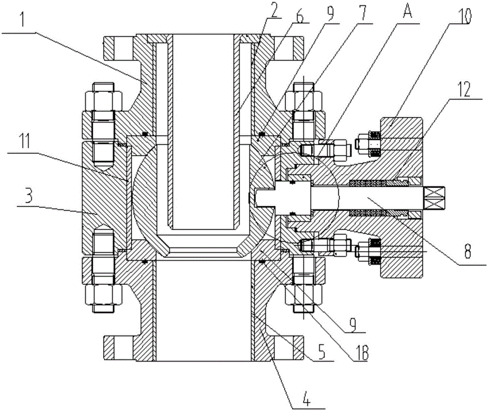
[0028] Such as figure 1 As shown, a floating multi-phase cut-off angle valve, hereinafter referred to as an angle valve, is used to control the flow of powder. The powder may be commonly used powder including coal powder, polysilicon powder and the like.

[0029] An rest angle valve includes upper flange 1, upper flange liner 2, valve body 3, lower flange 4, lower flange liner 5 and inlet conduit 6, the upper and lower flanges are connected to the valve body 3 by bolts and nuts. The upper flange liner 2 and the lower flange liner 5 are respectively embedded in the upper flange 1 and the lower flange 4 . The inner cavity at the top of the upper flange 1 is provided with an annular groove. The inlet conduit 6 extends from the upper flange liner 2 to the valve body 3. The shoulder at the upper end of the inlet conduit 6 just fits into the annular groove of the upper flange. The inlet conduit 6 The upper plane is flush with the upper plane of the upper flange, and the force on t...


PUM


Abstract

The invention discloses a floating type multi-phase cut-off repose angle valve. The floating type multi-phase cut-off repose angle valve comprises a valve body. A valve element with a valve rod is arranged in the valve body in a rotating mode. Valve bases are arranged between the valve element and an upper flange and between the valve element and a lower flange respectively. The valve element comprises a feed port, a discharge port and a side opening communicated with the feed port. The width of the side opening is larger than the diameter of an inlet guide pipe. When the discharge port of the valve element is parallel to the outlet of the inlet guide pipe, the floating type multi-phase cut-off repose angle valve is in the opened state, powder enters the valve element through the inlet guide pipe and then flows to a lower flange liner tube to be discharged, and powder conveying is achieved. When the repose angle valve needs to be closed so as to cut off powder conveying, the valve rod is rotated, the valve element is made to rotate by 90 degrees, the discharge port of the valve element is converted to being relatively perpendicular to the outlet of an inlet liner tube from being parallel to the outlet of the inlet liner tube, the gas phase is cut off firstly through the valve bases and the spherical valve element, and dust raising is prevented. The powder is accumulated on the inner wall of the valve element when falling down from the inlet guide pipe; due to the unique repose angle characteristic of the powder, the powder is unceasingly accumulated till the outlet of the inlet guide pipe is closed through the powder in an inner cavity of the spherical valve element, and the powder is cut off.

Description

technical field [0001] The invention relates to the technical field of powder conveying control valves. Background technique [0002] Valves are generally used to control material circulation and cut-off during pipeline transportation, but a small amount of powder will enter between the valve body and seat during the opening or closing of existing conventional valves (such as ball valves or gate valves), and the conventional valves will be in use. There are different degrees of wear and tear, and special working conditions will cause pollution of the conveying powder, and even damage the seal (valve seat, ball core) in severe cases, destroying the cut-off function of the valve, so most conventional valves are not suitable for powder delivery. Contents of the invention [0003] In order to solve the deficiencies in the prior art, the present invention provides a floating multi-phase cut-off angle-of-rest valve that utilizes the characteristics of the angle of repose of the...

Claims


Application Information

Patent Timeline
Patent Type & Authority Applications(China)
IPC IPC(8): F16K5/06F16K5/08
CPCF16K5/0663F16K5/0694F16K5/08
Inventor 杨光贤尹进杨如贤顾俊铭
Owner WUXI HAILI AUTOMATIC CONTROL ENG CO LTD
Why Eureka
Try Eureka