High-voltage DC bus box and high-voltage DC bus device

A technology of high-voltage direct current and junction box, which is applied in the direction of substation/switchgear board/panel/desk, busbar/line layout, electrical components, etc., and can solve problems such as unsightly appearance, complicated wiring process, and copper bar processing process , to achieve neat and orderly connections and solve the effect of complicated wiring

Active Publication Date: 2015-12-02
深圳创芯技术股份有限公司
View PDF3 Cites 4 Cited by
  • Summary
  • Abstract
  • Description
  • Claims
  • Application Information

AI Technical Summary

Problems solved by technology

[0002] In the existing market, for high-voltage DC power supply systems, power-operated power systems, and communication power supply systems, the confluence between AC and DC distribution switches can be roughly divided into: 1. Copper bar confluence (positive and negative poles, or AC ABC three-phase each One pole is connected to the main road copper bar through a small bent copper bar or copper teeth), among which there are various types of non-standard copper bars, the processing technology of copper bars is complicated, and the processing cost is too high; 2. Bus bars (positive and negative poles, or AC ABC three-phase), the bus bar cannot meet the diverse needs of customers, and has limitations; 3. Cable jumper connection (positive and negative poles, or AC ABC three-phase each pole open circuit is shorted by cable jumper), However, the cable jumper connection has the problems of complicated wiring process, unsightly appearance and high labor cost.

Method used


Image

  • High-voltage DC bus box and high-voltage DC bus device
  • High-voltage DC bus box and high-voltage DC bus device
  • High-voltage DC bus box and high-voltage DC bus device

Examples


Embodiment 1

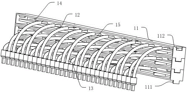
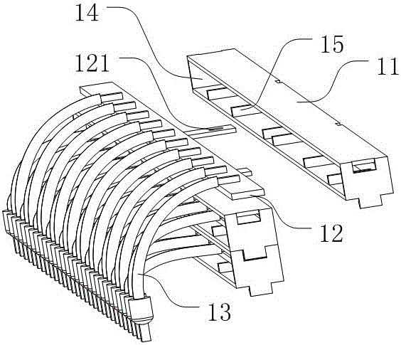
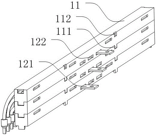
[0023] An embodiment of the present invention provides a high-voltage DC combiner box, such as figure 1 The schematic diagram of the stacked installation of three high-voltage DC combiner boxes is shown in the figure, as shown in figure 2 Shown is a schematic diagram of the explosion structure of one of the high-voltage DC combiner boxes, combined with image 3 , the high-voltage DC junction box includes a strip-shaped box body 11, and a busbar metal strip 12 is arranged along the length direction in the strip-shaped box body 11, and one side of the two sides of the box body 11 is provided along the length direction for connecting wires 13. To open the required opening 14, the bus bar 12 is provided with a terminal plate 121 and the terminal plate 121 extends out of the box body 11 in the horizontal direction to the side where the opening is not located. In this embodiment The middle strip box body 11 is located on the opposite side (back side) of the opening 14 and is provi...

Embodiment 2

[0029] This embodiment is improved on the basis of the above-mentioned embodiment 1. The only difference from the above-mentioned embodiment 1 is the stacking method of the boxes, such as Figure 4 As shown, it is only a schematic diagram of the assembly structure of the elongated box, omitting parts such as wires and busbars. The top of the elongated box 11 is provided with a slider 113 along the length direction, and the bottom of the box is provided with The chute 114 matched with the slider, when two adjacent boxes 11 are stacked and installed, the chute 114 at the bottom of the upper box fits and matches with the slider 113 of the lower box. In order to ensure a stable installation between the upper and lower boxes, the longitudinal section of the slider is T-shaped, and the longitudinal section of the chute is a matching T-shaped slot with the slider. When installing, the upper and lower boxes slide upwards in the front and rear Easy to install and disassemble.

Embodiment 3

[0031] An embodiment of the present invention provides a high-voltage DC confluence device, such as Figure 5As shown, it includes: the mounting base 51 and the high-voltage DC junction box 52 described in the above-mentioned embodiment 1. The DC junction box 52 is installed on the top surface of the mounting base 51, and each open space 53 is connected to the corresponding position of the bus bar through wires, that is, the plane where each wire is located is perpendicular to the bus bar, which can ensure the use of the shortest possible time. The wires are connected to the open circuit and the bus metal strip, thereby saving the wires and ensuring that the wires are neatly connected between the open circuit and the bus metal strip. The front end face of the mounting seat referred to in this embodiment is the end face with the opening of the junction box 52 in the same direction. Here, this direction is defined for the convenience of understanding the technical solution. In p...


PUM


Abstract

The invention discloses a high-voltage DC bus box and a high-voltage DC bus device. The high-voltage DC bus box comprises at least one strip-shaped box body. A bus metallic bar is disposed in the strip-shaped box body along the length direction. An opening is disposed on one of both sides of the box body along the length direction and is used by wires to be connected an air switches. The bus metallic bar is provided with a wiring end plate and the wiring end plate extends, in the horizontal direction, to the side, where the opening is not located, of the box body to be out of the box body. The bus metallic bar is used as a connecting end connected with air switch wires such that a connecting point is transformed to a connecting line. As a result, problems of complex wire arrangement and tangled wire connection in the prior art are solved and the air switch wires are connected in a tidy and ordered manner. The box bodies can be superposed in order that a large amount of wires can be arranged.

Description

technical field [0001] The invention relates to the technical field of high-voltage direct current power supply systems, in particular to a high-voltage direct current combiner box and equipment. Background technique [0002] In the existing market, for high-voltage DC power supply systems, power-operated power systems, and communication power supply systems, the confluence between AC and DC distribution switches can be roughly divided into: 1. Copper bar confluence (positive and negative poles, or AC ABC three-phase each One pole is connected to the main road copper bar through a small bent copper bar or copper teeth), among which there are various types of non-standard copper bars, the processing technology of copper bars is complicated, and the processing cost is too high; 2. Bus bars (positive and negative poles, or AC ABC three-phase), the bus bar cannot meet the diverse needs of customers, and has limitations; 3. Cable jumper connection (positive and negative poles, or...

Claims


Application Information

Patent Timeline
Patent Type & Authority Applications(China)
IPC IPC(8): H02B1/20H02B1/052H02B1/04H01R25/16H01R13/72
CPCH01R13/72H01R25/165H02B1/04H02B1/0526H02B1/20
Inventor 曾斌强彭江明
Owner 深圳创芯技术股份有限公司
Why Eureka
Try Eureka