Panoramic photograph generation method and device

A panorama and photo technology, applied in the field of panorama photo generation methods and devices, can solve the problems of inability to take panorama shots, users missing panorama materials or video materials, and inability to take both video and panorama shots into consideration.

Inactive Publication Date: 2015-12-02
XIAOMI INC
7 Cites 16 Cited by

AI-Extracted Technical Summary

Problems solved by technology

Since the camera cannot record video during panoramic shooting, and cannot take panoramic shooting when recording video, it c...

Method used

[0130] The processing component 602 generally controls the overall operations of the device 600, such as operations associated with display, telephone calls, data communications, camera operations, and recording operations. The processing element 602 may include one or more processors 620 to execute instructions to complete all or part of th...

Abstract

The invention discloses a panoramic photograph generation method and device. The method comprises: determining the work state information of a shooting device in a shooting video file process; determining whether the work state information accords with a preset condition, and extracting the video fragment corresponding to the work state information if the work state information accords with the preset condition; and generating a panoramic photograph through the video fragment. The technical scheme can ensure that video materials according with a panorama mode are generated into panoramic photographs, and provide different visual experiences for users through video files.

Application Domain

Television system detailsImage analysis +5

Technology Topic

Work statusComputer graphics (images) +2

Image

  • Panoramic photograph generation method and device
  • Panoramic photograph generation method and device
  • Panoramic photograph generation method and device

Examples

  • Experimental program(1)

Example Embodiment

[0057] The exemplary embodiments will be described in detail here, and examples thereof are shown in the accompanying drawings. When the following description refers to the accompanying drawings, unless otherwise indicated, the same numbers in different drawings represent the same or similar elements. The implementation manners described in the following exemplary embodiments do not represent all implementation manners consistent with the present invention. Rather, they are merely examples of devices and methods consistent with some aspects of the present invention as detailed in the appended claims.
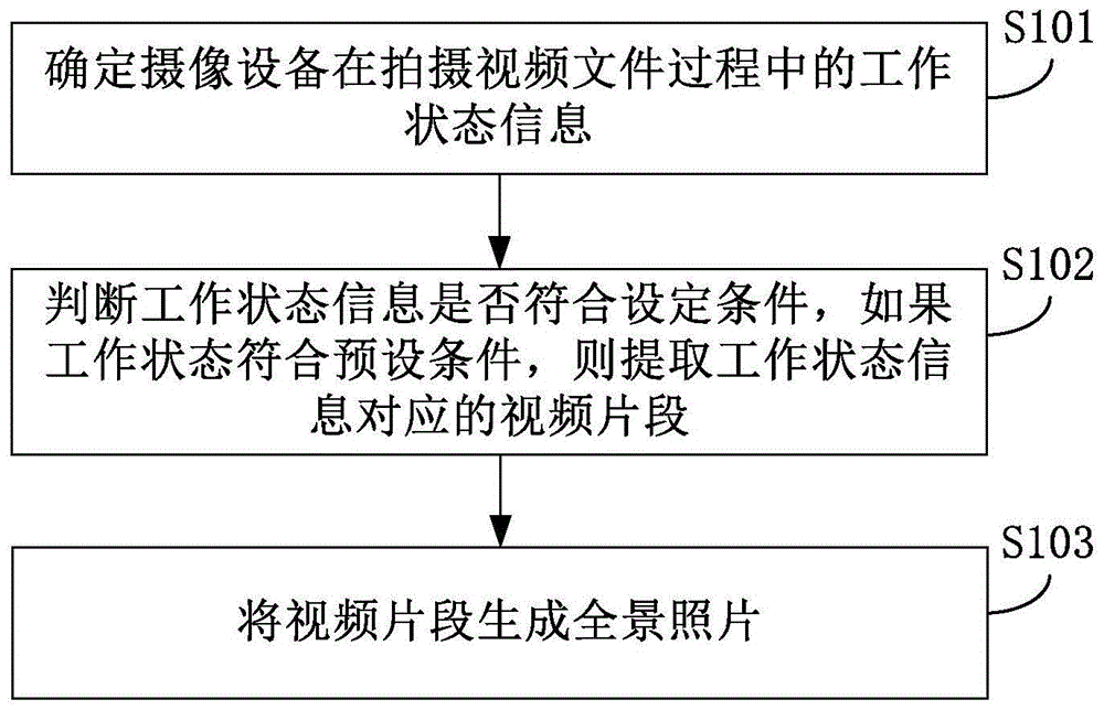
[0058] Figure 1A Is a flowchart of a method for generating a panoramic photo according to an exemplary embodiment, Figure 1B It is a scene diagram of a method for generating a panoramic photo according to an exemplary embodiment; the method for generating a panoramic photo can be applied to terminal devices (for example, video cameras, cameras, smart phones and tablets with cameras, and capable of playing video File on a desktop computer, etc.), it can be implemented by installing an application (app) or software on the terminal device, such as Figure 1A As shown, the method for generating the panoramic photo includes the following steps S101-S103:
[0059] In step S101, the working status information of the imaging device in the process of shooting a video file is determined.
[0060] In an embodiment, the working status information of the camera device during the shooting of the video file may be stored in the video file in a set format, or may be stored in a configuration corresponding to the video file for recording working status information. File. In an embodiment, the working status information may include the horizontal movement speed and the horizontal movement angle of the camera device during the shooting process.
[0061] In step S102, it is determined whether the work status information meets the set conditions, and if the work status meets the preset conditions, then the video clips corresponding to the work status information are extracted.
[0062] In an embodiment, the horizontal movement speed and horizontal movement angle of the camera device during the video shooting process can be used to determine whether the working status information meets the set conditions. For example, when the horizontal movement speed of the camera device is less than a first preset threshold and When the horizontal motion angle is greater than the second preset threshold, it is determined that the video segment meets the setting conditions for generating a panoramic photo.
[0063] In step S103, a panoramic photo is generated from the video segment.
[0064] In an embodiment, a panoramic photo can be generated from a video clip by a panoramic photo generation method in the related art, which is not described in detail in this disclosure.
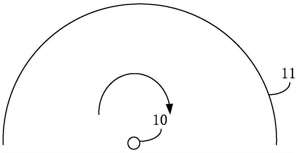
[0065] Such as Figure 1B As shown, when the imaging device 10 shoots along the direction of the arrow in the figure, the field of view of the video image formed on the charge-coupled device (CCD) of the imaging device 10 is shown as reference number 11. During the shooting process, the horizontal movement speed and horizontal movement angle of the camera device 10 are obtained through the gyroscope in the camera device 10. When the horizontal movement speed of the camera device 10 is less than the first preset threshold, the captured video clip can be guaranteed The corresponding panoramic photos have higher definition. When the horizontal movement angle of the camera device 10 is greater than the second preset threshold, it can be ensured that the panoramic photo corresponding to the video segment has a larger field of view.
[0066] In this embodiment, by extracting the video clips corresponding to the working status information that meets the preset conditions in the video file, the video clips are generated into panoramic photos, which changes the implementation method of shooting panoramic photos in the panoramic mode in related technologies to ensure that the The video material in the video file that conforms to the panoramic mode generates a panoramic photo, thereby bringing a different visual experience to the user through the video file.
[0067] In an embodiment, the working state information may include horizontal movement speed and horizontal movement angle, and determining the working state information of the camera equipment during the video shooting process may include:
[0068] Determine the horizontal movement speed of the camera equipment during the video shooting process through the gyroscope;
[0069] The gyroscope is used to determine the horizontal movement angle of the camera device during the video shooting process.
[0070] In an embodiment, determining whether the work status information meets a preset condition may include:
[0071] Determine whether the horizontal movement speed is less than the first preset threshold;
[0072] Determine whether the horizontal movement angle is greater than the second preset threshold;
[0073] If the horizontal movement speed is less than the first preset threshold and the horizontal movement angle is greater than the second preset threshold, it is determined that the working state information meets the preset condition.
[0074] In an embodiment, the method may further include:
[0075] If the horizontal movement speed is greater than the first preset threshold, and/or the horizontal movement angle is less than the second preset threshold, it is prompted that the video segment for generating the panoramic photo cannot be determined in the video file.
[0076] In an embodiment, the extracting the video clip corresponding to the working status information may include:
[0077] Determine the start time point of the horizontal exercise and the end time point of the horizontal exercise;
[0078] The video segment is determined according to the start time point and the end time point.
[0079] In an embodiment, the working state information may include horizontal movement speed and horizontal movement angle, and determining the working state information of the camera equipment during the video shooting process may include:
[0080] Determine the horizontal movement speed and the horizontal movement angle of the camera device during the video shooting process from the configuration file corresponding to the video file.
[0081] For details on how to generate panoramic photos from video files, please refer to the subsequent embodiments.
[0082] So far, the above-mentioned method provided by the embodiments of the present disclosure can ensure that the panoramic photo is generated from the video material in the video file that meets the panoramic mode, so as to bring a different visual experience to the user through the video file.
[0083] Specific embodiments are used below to illustrate the technical solutions provided by the embodiments of the present disclosure.
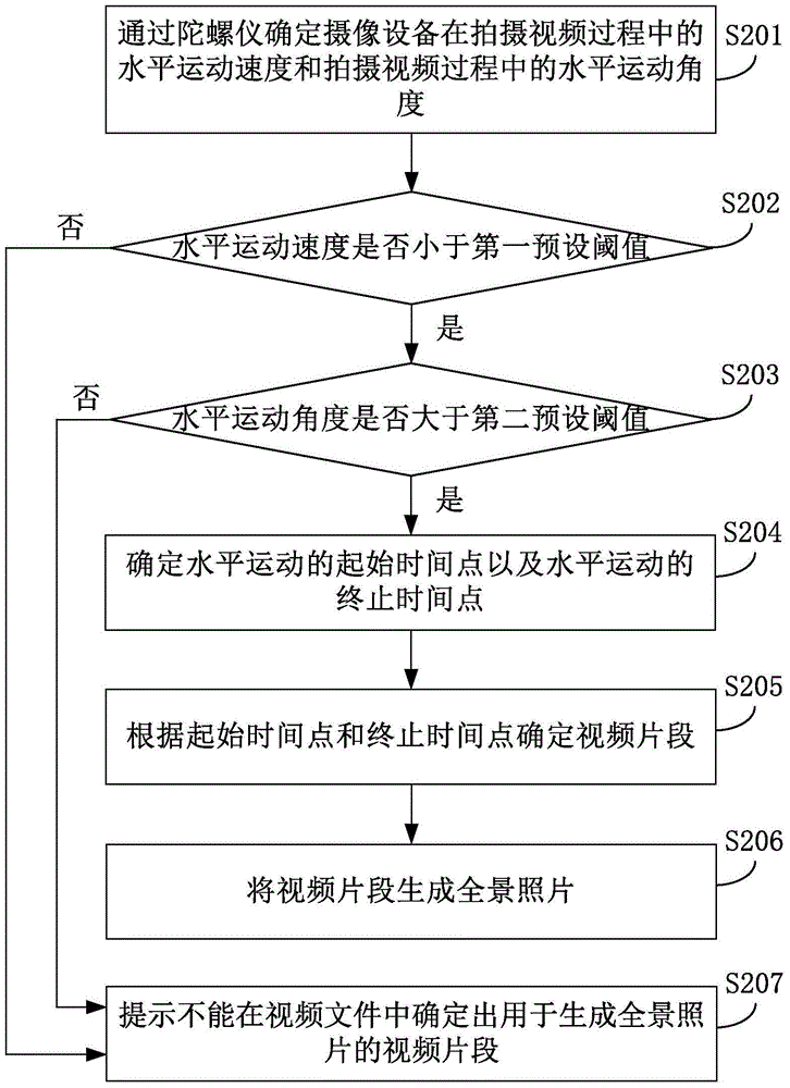
[0084] figure 2 It is a flowchart of a method for generating a panoramic photo according to an exemplary embodiment one; this embodiment uses the above-mentioned method provided in the embodiments of the present disclosure, and takes the camera device to generate a panoramic photo while shooting a video file as an example and combines Figure 1B Give exemplary instructions, such as figure 2 As shown, including the following steps:
[0085] In step S201, a gyroscope is used to determine the horizontal movement speed and the horizontal movement angle of the imaging device during the video shooting process.
[0086] In step S202, it is determined whether the horizontal movement speed is less than a first preset threshold, if the horizontal movement speed is less than the first preset threshold, step S203 is executed, and if the horizontal movement speed is greater than or equal to the first preset threshold, step S207 is executed.
[0087] In step S203, it is determined whether the horizontal movement angle is greater than the second preset threshold, if the horizontal movement angle is greater than the second preset threshold, step S204 is executed, and if the horizontal movement angle is less than or equal to the second preset threshold, step S207 is executed.
[0088] In an embodiment, the first preset threshold and the second preset threshold may be empirical values, as long as the horizontal movement speed and horizontal movement angle of the camera device can be ensured to ensure the image quality of the panoramic photo.
[0089] In step S204, if the horizontal movement angle is greater than the second preset threshold, the start time point of the horizontal movement and the end time point of the horizontal movement are determined.
[0090] In step S205, the video segment is determined according to the start time point and the end time point.
[0091] In an embodiment, the start time point when the horizontal movement starts and the end time point when the horizontal movement is terminated by the camera device can be recorded by the camera device, and the start time point and the end time point are set to The format is recorded in the video file.
[0092] In step S206, a panoramic photo is generated from the video segment.
[0093] In step S207, it is prompted that the video segment used to generate the panoramic photo cannot be determined in the video file.
[0094] Take the camera device 10 shooting a movie as an example for illustrative description, such as Figure 1B As shown, the lens of the camera device 10 moves horizontally with the camera position and the movement speed is slow. In addition, in the entire shooting scene, the art department will arrange the light and the environment, so that the light and illumination of the environment where the camera device 10 is located is darkened. Even, it is ensured that there are qualified video clips in the movie shot by the camera device 10, so that the panoramic photos generated by the video clips are used as the movie posters.
[0095] For example, in the process of shooting a movie, the camera device 10 obtains the horizontal movement speed and the horizontal movement angle of the camera device 10 during the video shooting process through the gyroscope. When it is detected that the horizontal movement speed of the camera device 10 is less than the first When the preset threshold and the horizontal motion angle are greater than the second preset threshold, the corresponding video segment is marked, so as to generate a panoramic photo from the video segment according to the marking.
[0096] In this embodiment, when the camera device detects that the horizontal motion speed is less than the first preset threshold and the horizontal motion angle is greater than the second preset threshold in the process of shooting the video file, the camera device can make the corresponding video clip Generate panoramic photos, so as to realize that while shooting videos, it is possible to generate panoramic photos from video clips corresponding to better panoramic materials, which takes into account both video shooting and panoramic shooting.
[0097] image 3 It is a flowchart of a method for generating a panoramic photo according to an exemplary embodiment two; this embodiment uses the above-mentioned method provided in the embodiments of the present disclosure to take a video file with a camera device and then generate a panoramic photo by generating the video file on the terminal device. Take the photo as an example for illustrative explanation, such as image 3 As shown, including the following steps:
[0098] In step S301, the horizontal movement speed and the horizontal movement angle of the camera device during the video shooting process are determined from the configuration file corresponding to the video file.
[0099] In step S302, it is determined whether the horizontal movement speed is less than a first preset threshold, if the horizontal movement speed is less than the first preset threshold, step S303 is executed, and if the horizontal movement speed is greater than or equal to the first preset threshold, step S307 is executed.
[0100] In step S303, it is determined whether the horizontal movement angle is greater than the second preset threshold, if the horizontal movement angle is greater than the second preset threshold, step S304 is executed, and if the horizontal movement angle is less than or equal to the second preset threshold, step S307 is executed.
[0101] For the description of the first preset threshold and the second preset threshold, please refer to the above figure 2 The related description in the illustrated embodiment will not be detailed here.
[0102] In step S304, if the horizontal movement angle is greater than the second preset threshold, the start time point of the horizontal movement and the end time point of the horizontal movement are determined.
[0103] In step S305, the video segment is determined according to the start time point and the end time point.
[0104] In step S306, a panoramic photo is generated from the video segment.
[0105] In step S307, it is prompted that the video segment used to generate the panoramic photo cannot be determined in the video file.
[0106] Take the terminal device that has acquired the movie shot by the camera device 10 as an example for illustrative description. The terminal device can read the horizontal movement speed of the camera device during the video shooting process and the video shooting process from the configuration file corresponding to the video file. When it is detected that the horizontal movement speed of the imaging device 10 is less than the first preset threshold and the horizontal movement angle is greater than the second preset threshold, determine the start time point of the horizontal movement and the end time point of the horizontal movement, and The video clips corresponding to the start time point and the end time point generate panoramic photos.
[0107] For example, the duration of a movie shot by the camera device 10 is 60 minutes, and the terminal device detects that the horizontal movement speed of the camera device 10 is less than the first preset threshold and the horizontal movement angle is greater than the second preset threshold between 45 minutes and 50 minutes. At this time, a panoramic photo can be generated from the video clips corresponding to 45 minutes to 50 minutes of the movie.
[0108] In this embodiment, the terminal device can obtain from the configuration file of the video file the horizontal movement speed and the horizontal movement angle of the camera in the process of shooting the video file and the horizontal movement angle in the process of shooting the video. In the case of a preset threshold and the horizontal motion angle is greater than the second preset threshold, the terminal device generates a panoramic photo from the corresponding video segment, thereby realizing that the video segment with better panoramic material in the video file can be generated into a panoramic photo, and both Video shooting and panoramic shooting.
[0109] Figure 4 Is a block diagram of an apparatus for generating panoramic photos according to an exemplary embodiment, such as Figure 4 As shown, the panoramic photo generating device includes:
[0110] The determining module 41 is configured to determine the working status information of the camera device in the process of shooting video files;
[0111] The video extraction module 42 is configured to determine whether the work status information determined by the determination module 41 meets the set conditions, and if the work status information meets the preset conditions, extract the video clips corresponding to the work status information;
[0112] The panoramic photo generating module 43 is configured to generate a panoramic photo from the video segment determined by the video extraction module 42.
[0113] Figure 5 It is a block diagram showing another panoramic photo generating device according to an exemplary embodiment, such as Figure 5 Shown in the above Figure 4 On the basis of the illustrated embodiment, in an embodiment, the working status information includes the horizontal movement speed and the horizontal movement angle, and the determination module 41 may include:
[0114] The first determining sub-module 411 is configured to determine the horizontal movement speed of the camera device during the video shooting process through the gyroscope;
[0115] The second determining sub-module 412 is configured to determine the horizontal movement angle of the camera device during the video shooting process through the gyroscope.
[0116] In an embodiment, the video extraction module 42 may include:
[0117] The third determining sub-module 421 is configured to determine whether the horizontal movement speed determined by the first determining sub-module 411 is less than a first preset threshold;
[0118] The fourth determining sub-module 422 is configured to determine whether the horizontal motion angle determined by the second determining sub-module 412 is greater than a second preset threshold;
[0119] The fifth determining submodule 423 is configured to determine the working state if the horizontal motion speed determined by the third determining submodule 421 is less than the first preset threshold and the horizontal motion angle determined by the fourth determining submodule 422 is greater than the second preset threshold The information meets the preset conditions.
[0120] In an embodiment, the device may further include:
[0121] The prompting module 44 is configured to prompt if the horizontal movement speed determined by the first determining sub-module 411 is greater than a first preset threshold, and/or the horizontal movement angle determined by the second determining sub-module 412 is less than a second preset threshold Determine the video segment used to generate the panoramic photo in the video file.
[0122] In an embodiment, the video extraction module 42 may include:
[0123] The sixth determining sub-module 424 is configured to determine the starting time point of the horizontal movement and the ending time point of the horizontal movement after the fifth determining sub-module 423 determines that the preset condition is met;
[0124] The seventh determining submodule 425 is configured to determine the video segment according to the starting time point and the ending time point determined by the sixth determining submodule 424.
[0125] In an embodiment, the working status information includes horizontal movement speed and horizontal movement angle, and the determining module 41 includes:
[0126] The eighth determining sub-module 413 is configured to determine the horizontal movement speed and the horizontal movement angle of the camera device during the video shooting process from the configuration file corresponding to the video file.
[0127] Regarding the device in the foregoing embodiment, the specific manner in which each module performs operation has been described in detail in the embodiment of the method, and detailed description will not be given here.
[0128] Image 6 It is a block diagram showing a device for generating panoramic photos according to an exemplary embodiment. For example, the device 600 may be a mobile phone, a computer, a digital broadcasting terminal, a messaging device, a game console, a tablet device, a medical device, a fitness device, a personal digital assistant, etc.
[0129] Reference Image 6 , The device 600 may include one or more of the following components: a processing component 602, a memory 604, a power supply component 606, a multimedia component 608, an audio component 610, an input/output (I/O) interface 612, a sensor component 614, and a communication component 616.
[0130] The processing component 602 generally controls the overall operations of the device 600, such as operations associated with display, telephone calls, data communications, camera operations, and recording operations. The processing element 602 may include one or more processors 620 to execute instructions to complete all or part of the steps of the foregoing method. In addition, the processing component 602 may include one or more modules to facilitate the interaction between the processing component 602 and other components. For example, the processing component 602 may include a multimedia module to facilitate the interaction between the multimedia component 608 and the processing component 602.
[0131] The memory 604 is configured to store various types of data to support the operation of the device 600. Examples of such data include instructions for any application or method operating on the device 600, contact data, phone book data, messages, pictures, videos, etc. The memory 604 can be implemented by any type of volatile or nonvolatile storage device or a combination thereof, such as static random access memory (SRAM), electrically erasable programmable read-only memory (EEPROM), erasable and Programmable read only memory (EPROM), programmable read only memory (PROM), read only memory (ROM), magnetic memory, flash memory, magnetic or optical disk.
[0132] The power component 606 provides power to various components of the device 600. The power component 606 may include a power management system, one or more power supplies, and other components associated with generating, managing, and distributing power for the device 600.
[0133] The multimedia component 608 includes a screen that provides an output interface between the device 600 and the user. In some embodiments, the screen may include a liquid crystal display (LCD) and a touch panel (TP). If the screen includes a touch panel, the screen may be implemented as a touch screen to receive input signals from the user. The touch panel includes one or more touch sensors to sense touch, sliding, and gestures on the touch panel. The touch sensor may not only sense the boundary of the touch or slide action, but also detect the duration and pressure related to the touch or slide operation. In some embodiments, the multimedia component 608 includes a front camera and/or a rear camera. When the device 600 is in an operation mode, such as a shooting mode or a video mode, the front camera and/or the rear camera can receive external multimedia data. Each front camera and rear camera can be a fixed optical lens system or have focal length and optical zoom capabilities.
[0134] The audio component 610 is configured to output and/or input audio signals. For example, the audio component 610 includes a microphone (MIC). When the device 600 is in an operation mode, such as a call mode, a recording mode, and a voice recognition mode, the microphone is configured to receive external audio signals. The received audio signal can be further stored in the memory 604 or sent via the communication component 616. In some embodiments, the audio component 610 further includes a speaker for outputting audio signals.
[0135] The I/O interface 612 provides an interface between the processing component 602 and a peripheral interface module. The above-mentioned peripheral interface module may be a keyboard, a click wheel, a button, and the like. These buttons may include but are not limited to: home button, volume button, start button, and lock button.
[0136] The sensor component 614 includes one or more sensors for providing the device 600 with various aspects of status assessment. For example, the sensor component 614 can detect the on/off status of the device 600 and the relative positioning of the components. For example, the component is the display and the keypad of the device 600. The sensor component 614 can also detect the position change of the device 600 or a component of the device 600. , The presence or absence of contact between the user and the device 600, the orientation or acceleration/deceleration of the device 600 and the temperature change of the device 600. The sensor component 614 may include a proximity sensor configured to detect the presence of nearby objects when there is no physical contact. The sensor component 614 may also include a light sensor, such as a CMOS or CCD image sensor, for use in imaging applications. In some embodiments, the sensor component 614 may also include an acceleration sensor, a gyroscope sensor, a magnetic sensor, a pressure sensor or a temperature sensor.
[0137] The communication component 616 is configured to facilitate wired or wireless communication between the apparatus 600 and other devices. The device 600 can access a wireless network based on a communication standard, such as WiFi, 2G, or 3G, or a combination thereof. In an exemplary embodiment, the communication component 616 receives a broadcast signal or broadcast related information from an external broadcast management system via a broadcast channel. In an exemplary embodiment, the communication component 616 further includes a near field communication (NFC) module to facilitate short-range communication. For example, the NFC module can be implemented based on radio frequency identification (RFID) technology, infrared data association (IrDA) technology, ultra-wideband (UWB) technology, Bluetooth (BT) technology and other technologies.
[0138] In an exemplary embodiment, the apparatus 600 may be implemented by one or more application specific integrated circuits (ASIC), digital signal processors (DSP), digital signal processing equipment (DSPD), programmable logic devices (PLD), field programmable A gate array (FPGA), controller, microcontroller, microprocessor, or other electronic components are implemented to implement the above methods.
[0139] In an exemplary embodiment, there is also provided a non-transitory computer-readable storage medium including instructions, such as the memory 604 including instructions, which may be executed by the processor 620 of the device 600 to complete the foregoing method. For example, the non-transitory computer-readable storage medium may be ROM, random access memory (RAM), CD-ROM, magnetic tape, floppy disk, optical data storage device, etc.
[0140] After considering the specification and practicing the disclosure disclosed herein, those skilled in the art will easily think of other embodiments of the present disclosure. This application is intended to cover any variations, uses, or adaptive changes of the present disclosure. These variations, uses, or adaptive changes follow the general principles of the present disclosure and include common knowledge or conventional technical means in the technical field not disclosed in the present disclosure. . The description and the embodiments are only regarded as exemplary, and the true scope and spirit of the present disclosure are pointed out by the following claims.
[0141] It should be understood that the present disclosure is not limited to the precise structure that has been described above and shown in the drawings, and various modifications and changes can be made without departing from its scope. The scope of the present disclosure is only limited by the appended claims.

PUM

no PUM

Description & Claims & Application Information

We can also present the details of the Description, Claims and Application information to help users get a comprehensive understanding of the technical details of the patent, such as background art, summary of invention, brief description of drawings, description of embodiments, and other original content. On the other hand, users can also determine the specific scope of protection of the technology through the list of claims; as well as understand the changes in the life cycle of the technology with the presentation of the patent timeline. Login to view more.
Why Eureka
Try Eureka