

Fuel injection valve
A technology of fuel injection valve and fuel, which is applied in the direction of fuel injection device, special fuel injection device, charging system, etc. It can solve the problem of shrinking cavity flow path area, achieve the effect of increasing the degree of freedom and promoting atomization
- Summary
- Abstract
- Description
- Claims
- Application Information
AI Technical Summary
Problems solved by technology
Method used
Image

Examples
Embodiment approach 1
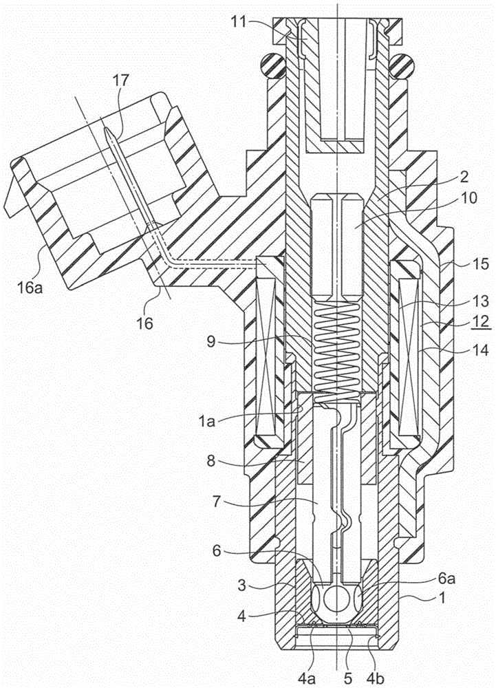
[0035] figure 1 is a cross-sectional view along the axis of the fuel injection valve according to Embodiment 1 of the present invention, and fuel is fed from figure 1 The upper end of the fuel injection valve flows downward. In the drawing, a cylindrical fixed iron core 2 is fixed to an upper end portion of a magnetic tube 1 . The magnetic tube 1 and the fixed iron core 2 are arranged coaxially. The magnet tube 1 is press-fitted into the downstream end of the fixed iron core 2 and welded.
[0036] A valve seat 3 and an orifice plate 4 are fixed at the lower end of the magnetic tube 1 . The orifice plate 4 is provided with a plurality of injection holes 5 for injecting fuel. The nozzle holes 5 penetrate the nozzle hole plate 4 in the plate thickness direction.
[0037] The orifice plate 4 is inserted into the magnet tube 1 while being fixed to the downstream side end surface of the valve seat 3 by the first welding portion 4a, and then fixed to the magnet tube 1 by the sec...
Embodiment approach 2
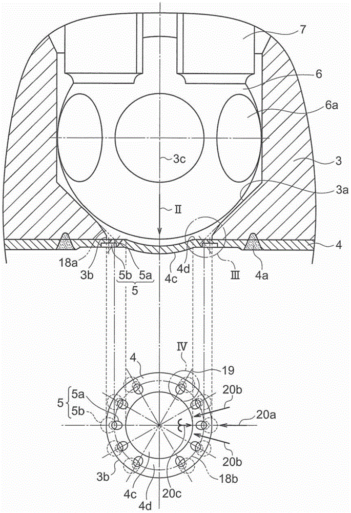
[0073] Next, Image 6 This is a cross-sectional view of the valve seat 3, orifice plate 4, and valve ball 6 of the fuel injection valve according to Embodiment 2 of the present invention, and a plan view showing the center of the orifice plate 4 (viewed from the valve ball 6 side along arrow VI). The figure of the part exposed in the fuel flow path) is shown in combination, Figure 7 will be Image 6 The enlarged cross-sectional view of Part VII, Figure 8 will be Image 6 The enlarged top view of Part VIII.
[0074] In the first embodiment, the convex portion 4c is provided at the center of the orifice plate 4, but in the second embodiment, the center of the orifice plate 4 is flat. In addition, in Embodiment 2, the front end portion of the valve ball 6 is provided with a flat portion 6 b parallel (or substantially parallel) to the orifice plate 4 . The flat portion 6 b faces the center of the upstream end surface of the nozzle hole plate 4 . When projected vertically o...
Embodiment approach 3
[0081] Next, Figure 9 It is an enlarged cross-sectional view showing the injection hole 5 of the fuel injection valve according to Embodiment 3 of the present invention. In Embodiment 3, in the flow path of the injection hole main body 5a, a cylindrical portion 5f having the smallest cross-sectional area is provided between the inlet and the outlet of the injection hole main body 5a. Other structures are the same as those in Embodiment 1.
[0082] In such a fuel injection valve, since the flow rate of fuel in the injection hole 5 depends on the cross-sectional area of the cylindrical portion 5f, the flow rate deviation caused by the positional deviation of the injection hole main body 5a and the large diameter portion 5b can be suppressed.
[0083] The injection hole main body 5a of Embodiment 2 may also be provided with a cylindrical portion 5f. That is, Embodiments 2 and 3 can be combined.
PUM
 Abstract
Description
Claims
Application Information