
Cleaning tool for optical connector

A technology for optical connectors and cleaning tools, which is applied in the field of optical connector cleaning tools, can solve the problems of complex cleaning work of cleaning tools, and achieve the effects of simple structure, simplified operation, and reduced size

Active Publication Date: 2015-12-02
NTT ADVANCED TECH +1
View PDF7 Cites 19 Cited by
  • Summary
  • Abstract
  • Description
  • Claims
  • Application Information

AI Technical Summary

Problems solved by technology

[0012] The optical connector cleaning tool described in Patent Document 1 has a problem that the cleaning work is complicated

Method used


Image

  • Cleaning tool for optical connector
  • Cleaning tool for optical connector
  • Cleaning tool for optical connector

Examples


Embodiment Construction

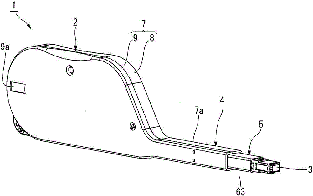
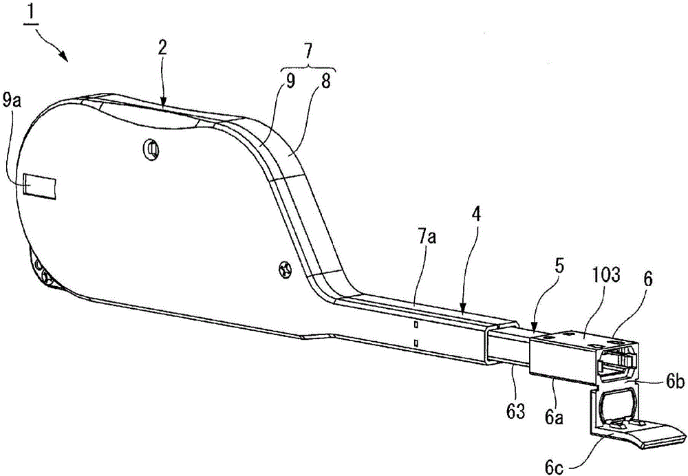
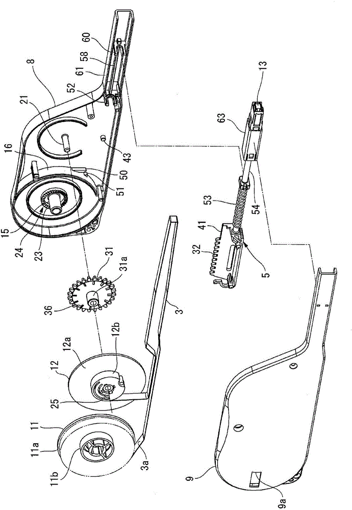
[0050] The following will refer to Figures 1 to 26 An embodiment of the optical connector cleaning tool according to the present invention will be described.

[0051] Such as figure 1 The optical connector cleaning tool 1 shown consists of a figure 1 The left handle 2. A user (not shown) holds handle 2 in his or her hand, and will figure 1 The cleaning cloth 3 with the exposed end on the right side is pressed against the connection end surface of the optical connector plug (not shown), thereby cleaning the connection end surface. In this embodiment, the direction toward the optical connector plug will be referred to as forward (towards figure 1to the lower right of the ), and the opposite direction will be called backward. Also, when explaining respective components to be described below, a member positioned forward as described above will be referred to as a front portion or a front side, and a member positioned backward will be referred to as a rear portion or a rear s...


PUM


Abstract

A supplying reel (11) having a belt-shaped cleaning cloth (3), and a winding bobbin (12) for winding the cleaning cloth (3) are provided. Also provided are a housing (7) for rotatably supporting the supplying reel (11) and the winding bobbin (12), a cleaning head (13) for contacting the cleaning cloth (3), and a pressing member (5) for supporting the cleaning head (13) and moving forward and backward with respect to the housing (7). Also provided are a slide spring (53) for urging the pressing member (5) forward, and a drive transmission mechanism for transmitting the action of the pressing member (5) to the winding bobbin (12). The drive transmission mechanism (33) has a pressing-member-(5)-side rack (32) and a winding-bobbin-(12)-side pinion. In the drive transmission mechanism (33), the pressing member (5) retreats with respect to the housing (7), thereby causing the winding bobbin (12) to rotate so that the cleaning cloth (3) is delivered. By the present invention, an optical connector plug can easily be cleaned by a simple structure that is reduced in size.

Description

technical field [0001] The present invention relates to an optical connector cleaning tool for cleaning a connection end face of an optical connector with a cleaning cloth. Background technique [0002] An example of this type of conventional optical connector cleaning tool is described in Patent Document 1, for example. The optical connector cleaning tool disclosed in Patent Document 1 includes a housing having a size that a user can hold in his or her hand; a cleaning tape accommodated in the housing; and a tool for supplying the cleaning tape. With supply mechanism. [0003] The housing has a narrow cylindrical portion. A cleaning head for pressing the cleaning tape against the optical connector is formed at the distal end of this barrel. The cleaning tape is pulled out from the supply reel housed in the housing to the front surface side of the cleaning head through the above-mentioned barrel portion. Furthermore, the cleaning tape is reversed by the cleaning head and...

Claims


Application Information

Patent Timeline
Patent Type & Authority Applications(China)
IPC IPC(8): G02B6/36B08B1/04
CPCG02B6/3866B08B1/006B08B1/143B08B1/30B08B2240/02B08B1/00
Inventor 鸭打辉正村上雅之小西正晃滨野毅信东海林节夫
Owner NTT ADVANCED TECH
Learn More