Magnet insertion device and method for rotor core magnet insertion hole

A technology of rotor iron core and insertion device, which is applied in the manufacture of stator/rotor body, electromechanical device, magnetic circuit, etc., can solve problems such as magnet pieces hanging

Active Publication Date: 2016-10-26
NISSAN MOTOR CO LTD
View PDF6 Cites 0 Cited by
  • Summary
  • Abstract
  • Description
  • Claims
  • Application Information

AI Technical Summary

Problems solved by technology

Therefore, there is a problem that, if the magnet piece comes into contact with the side wall of the magnet insertion hole, the posture of the magnet piece is inclined due to its frictional resistance, and the magnet piece is easily caught in the middle of the magnet insertion hole.

Method used


Image

  • Magnet insertion device and method for rotor core magnet insertion hole
  • Magnet insertion device and method for rotor core magnet insertion hole
  • Magnet insertion device and method for rotor core magnet insertion hole

Examples


Embodiment Construction

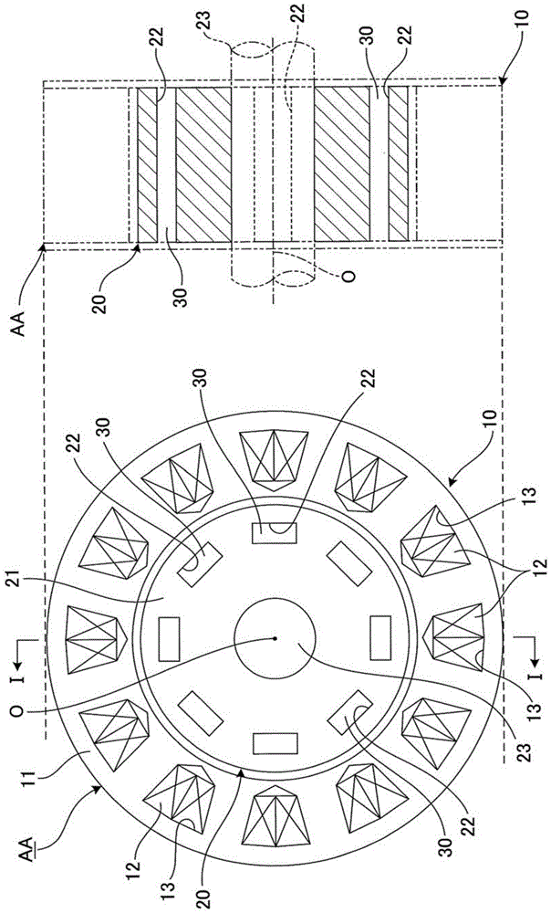
[0020] figure 1 It is a schematic configuration diagram showing the configuration of a main part of a rotating electrical machine provided with a rotor in which magnets are inserted into rotor core magnet insertion holes according to the present embodiment. exist figure 1 In , the figure on the left is a cross-sectional view of the rotating electrical machine, and the figure on the right is a side view. The rotary electric machine AA includes: an annular stator 10 constituting a part of an unillustrated casing; and a cylindrical rotor 20 arranged coaxially with the stator 10 . The rotary electric machine AA is, for example, an electric motor, and is used as a driving source of an electric vehicle or a hybrid vehicle. However, the rotating electric machine can also be a generator, and its use is not limited to automobiles.

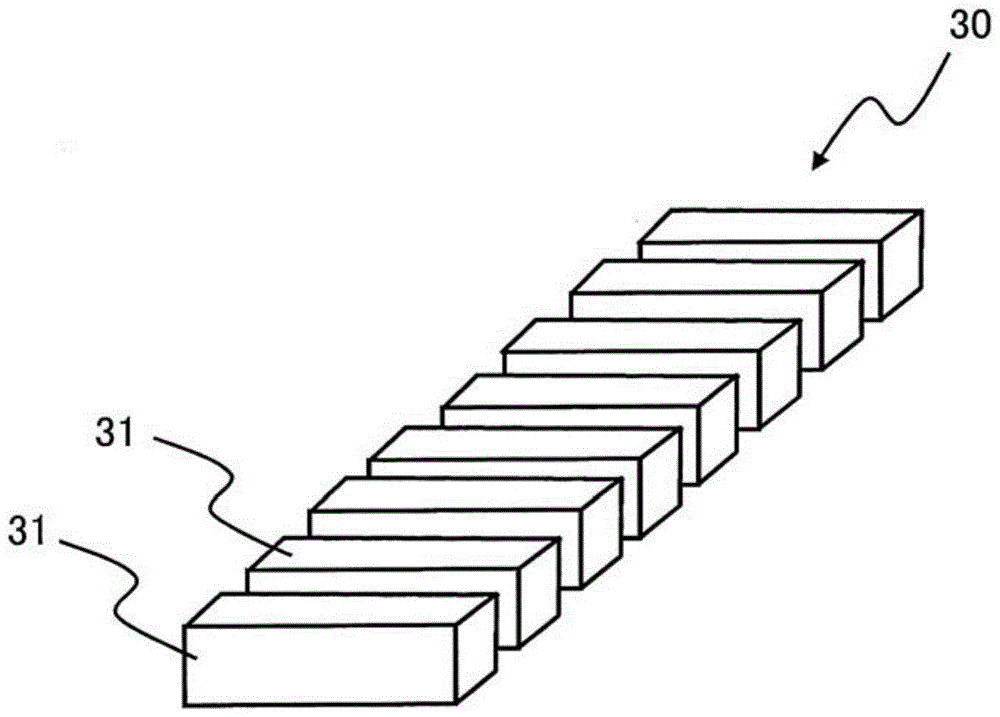
[0021] The stator 10 includes a stator core 11 and a plurality of coils 12 . The plurality of coils 12 are accommodated in slots 13 formed at equal a...


PUM


Abstract

A magnet inserting apparatus into magnet insertion slots of a rotor core is configured to arrange a guide tape (a belt-shaped member) along an inner wall surface of the magnet insertion slot, and the guide tape having a coefficient of friction smaller than that of the inner wall surface of the magnet insertion slot. The magnet inserting apparatus is configured to insert the magnet parts into the magnet insertion slot, the guide tape (the belt-shaped member) being arranged on the inner wall surface of the magnet insertion slot.

Description

technical field [0001] The present invention relates to a technique for inserting a magnet into a magnet insertion hole of a rotor core. Background technique [0002] Conventionally, a technique is known in which a long plate-shaped magnet formed by integrating a plurality of divided magnet pieces is used as a magnet inserted into a magnet insertion hole of a rotor core of a motor (see WO2001 / 095460A). As described above, the magnets to be inserted into the magnet insertion holes of the rotor core are formed as a plurality of magnet pieces, and the volume of each magnet piece is reduced, thereby reducing eddy currents generated by fluctuations in the applied magnetic field. [0003] Here, since a large manufacturing cost is generated when joining a plurality of magnet pieces to form a long plate shape, in order to reduce the cost, it is considered to abolish the process of joining a plurality of magnet pieces, and directly attach a plurality of magnet pieces to the rotor. T...

Claims


Application Information

Patent Timeline
Patent Type & Authority Patents(China)
IPC IPC(8): H02K15/03H02K1/27
CPCH02K1/276H02K15/03
Inventor 长谷川清大岛巧松下靖志堀晃久岸伦人关川岳
Owner NISSAN MOTOR CO LTD
Why Eureka
Try Eureka