Practical cultivator

A cultivator, a practical technology, applied in the field of agricultural machinery, can solve problems such as breakage, short service life, incomplete cultivation coverage, etc., and achieve the effect of full coverage and extended service life

Inactive Publication Date: 2015-12-09
张强
0 Cites 0 Cited by

AI-Extracted Technical Summary

Problems solved by technology

The defect of existing practical cultivating machine is that most of the transmission gears only have forward gears, and there is no reverse gear. When farming in the farmland, it will be very laborious and inconvenient to operate if the complete machine is reversed; The gears and axles in t...

Abstract

The invention discloses a practical cultivator which comprises a rack, an engine, a speed changing box, a handle assembly and a rotary tillage work mechanism. The engine, the speed changing box and the handle assembly are arranged on the rack. The rotary tillage work mechanism comprises a power output shaft, a tool apron fixed to the power output shaft and rotary blades fixedly arranged on the tool apron. The speed changing box comprises a box body and a transmission speed changing mechanism arranged in the box body. The practical cultivator is characterized in that the transmission speed changing mechanism comprises a gear changing shaft fixedly provided with a shifting fork, a power input shaft, an intermediate wheel shaft, a transmission shaft, a power input wheel, a gear shifting gear, an intermediate wheel installed on the intermediate wheel shaft, a transmission wheel and a chain wheel, wherein the power input wheel and the gear shifting gear are installed on the power input shaft, and the transmission wheel and the chain wheel are installed on the transmission shaft. The transmission shaft is further sleeved with a duplicate gear in a clearance mode, and the duplicate gear comprises a reverse gear and a small gear. The practical cultivator is provided with a reverse gear mechanism, the reverse action of the whole cultivator can be easily achieved, and the practical cultivator is complete in cultivating coverage and long in service life.

Application Domain

Tilling equipments

Technology Topic

SprocketEngineering +2

Image

  • Practical cultivator
  • Practical cultivator

Examples

  • Experimental program(1)

Example Embodiment

[0016] Examples:
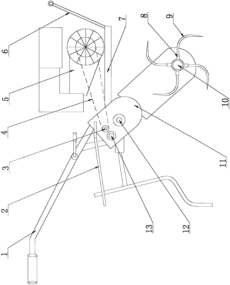
[0017] A practical cultivator, such as figure 1 As shown, it includes a frame 7 and an engine 5 arranged on the frame 7, a gearbox, a handle assembly 1, and a rotary tillage mechanism. The handle assembly 1 is arranged at the rear of the frame 7, and the front end of the frame 7 is provided with a bumper 6.
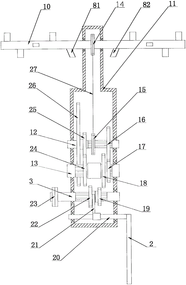
[0018] The rotary tillage mechanism includes a power output shaft 10, a power output wheel 14 fixed in the middle of the power output shaft 10, a tool holder 8 fixed on the power output shaft 10, and a rotary cutter 9 fixedly mounted on the tool holder 8. Among the knife holders, the two knife holders 81 and 82 located on both sides of the gearbox are inclined inward, and the inclination angle is 10°-20°. In this way, during the rotary tillage operation, the plot below the gearbox will not be dropped, leaving no dead corners.
[0019] Such as figure 2 As shown, the gearbox includes a box body 11 and a transmission and speed change mechanism arranged in the box body 11. The transmission transmission mechanism includes a gear shaft 20 fixedly installed with a shift fork 21, a power input shaft 3, an intermediate wheel shaft 13, a transmission shaft 12, and a power input wheel 23 and a shift gear mounted on the power input shaft 3, and are installed on the intermediate wheel shaft 13 on the intermediate wheel, the transmission wheel 16 and the sprocket 15 mounted on the transmission shaft 12. One end of the gear-hanging shaft 20 passes through the box body 11 and is fixedly connected to the gear-hanging rod 2. Both ends of the power input shaft 3, the intermediate wheel shaft 13, and the transmission shaft 12 are mounted on the shell wall of the box body 11 through bearings. The power input wheel 23 is in transmission connection with the power wheel of the engine through the belt 4.
[0020] The shift gear is a double gear, including a first gear 19 and a second gear 22, splined with the power input shaft 3, and the shift fork 21 is arranged between the first gear 19 and the second gear 22. The intermediate wheel includes a first gear intermediate wheel 18, a second gear intermediate wheel 24 and a transmission intermediate wheel 17, all of which are splined with the intermediate wheel shaft 13. Both the transmission wheel 16 and the sprocket 15 are splined with the transmission shaft 12. The first gear 19 and the second gear 22 can mesh with the first gear 18 and the second gear 24 respectively. The transmission gear 17 and the transmission gear 16 are constantly meshed, and the sprocket 15 and the force output gear 14 are drivingly connected by a chain 27.
[0021] The transmission shaft 12 is also hollow with a double gear, including a reverse gear 26 and a pinion 25. The reverse gear 26 can mesh with the second gear 22, and the pinion 25 is constantly meshed with the second gear 24.
[0022] In order to enhance the wear resistance of the transmission transmission mechanism and prolong its service life, compared with the transmission transmission mechanism of the existing practical cultivator, the present invention reduces the number of teeth of each gear, the corresponding tooth thickness is increased, and each wheel shaft is thickened. The diameter of the mounting hole of the corresponding gears is also increased. Wherein, the number of teeth of the first gear 19 is 17, and the number of teeth of the first gear 18 matched with it is 47; the number of teeth of the second gear 22 is 20, and the number of teeth of the second gear 22 is matched with it. The number of teeth of the wheel 24 is 44; the number of teeth of the transmission intermediate wheel 17 is 14, and the number of teeth of the transmission wheel 16 that is constantly meshed with it is 48. The diameter of the power input shaft 3 is 22 mm. The diameter of the intermediate shaft 13 is 25 mm.
[0023] The working principle of the transmission speed change of the present invention is as follows:
[0024] Start the engine 5, the power wheel of the engine 5 will drive the power input wheel 23 to rotate through the belt 4, and then drive the power input shaft 3. Before each gear is engaged, the belt 4 is loosened by the belt clutch, so that the power input shaft 3 loses power and stops rotating; after gear is engaged, the belt 4 is tightened by the belt clutch, and the power input shaft 3 gains power. Then, the power is transmitted to the power output wheel 14 through the transmission speed change mechanism, and then drives the rotary tillage mechanism to complete the rotary tillage operation.
[0025] When the shifting gear is between the first gear intermediate wheel 18 and the second gear intermediate wheel 24, the transmission speed change mechanism is in a neutral gear state.
[0026] The transmission process of the first gear is as follows: the gear shift lever 2 is operated, the gear shift shaft 20 drives the shift fork 21 to shift the shift gear, and the first gear 19 meshes with the first gear intermediate wheel 18. After the power input shaft 3 gains power, it drives the shift gear. The first gear 19 drives the first gear 18, the first gear 18 drives the transmission gear 17 through the intermediate gear shaft 13, and the transmission intermediate gear 17 drives the transmission shaft through the transmission wheel 16. 12, and then drive the sprocket 15, the sprocket 15 drives the power output wheel 14 through the chain 27, and then drives the rotary tillage mechanism to complete the rotary tillage operation.
[0027] The second gear transmission process is as follows: operate the gear shift lever 2 to make the gear shift shaft 20 drive the shift fork 21 to shift the shift gear, so that the second gear 22 meshes with the second gear intermediate wheel 24. After the power input shaft 3 gains power, it drives the shift gear. The second gear 22 drives the second gear intermediate wheel 24, the second gear intermediate wheel 24 drives the transmission intermediate wheel 17 through the intermediate wheel shaft 13, and the transmission intermediate wheel 17 drives the transmission shaft through the transmission wheel 16. 12, and then drive the sprocket 15, the sprocket 15 drives the power output wheel 14 through the chain 27, and then drives the rotary tillage mechanism to complete the rotary tillage operation.
[0028] The reverse gear transmission process is as follows: the gear shift lever 2 is operated, the shift shaft 20 drives the shift fork 21 to shift the shift gear, and the second gear 22 meshes with the reverse gear 26. After the power input shaft 3 gains power, it drives the shift gear, the second gear 22 drives the reverse gear 26, the reverse gear 26 drives the pinion 25, the pinion 25 drives the first gear 18, and the first gear 18 passes through the intermediate wheel shaft. 3 Drive the transmission intermediate wheel 17, which drives the transmission shaft 12 through the transmission wheel 16, and then drives the sprocket 15. The sprocket 15 transmits the power output wheel 14 through the chain 27, and the power output wheel 14 drives the rotary tillage operation mechanism to rotate in reverse , And then complete the reversing action of the whole machine.

PUM

PropertyMeasurementUnit
Diameter22.0mm
Diameter25.0mm

Description & Claims & Application Information

We can also present the details of the Description, Claims and Application information to help users get a comprehensive understanding of the technical details of the patent, such as background art, summary of invention, brief description of drawings, description of embodiments, and other original content. On the other hand, users can also determine the specific scope of protection of the technology through the list of claims; as well as understand the changes in the life cycle of the technology with the presentation of the patent timeline. Login to view more.

Similar technology patents

Software test system and method for digital reactor protection system of nuclear power plant

ActiveCN107480051Afull coverageRealize automatic generation
Owner:CHINA NUCLEAR POWER DESIGN COMPANY +2

Glomerocryst cubic boron nitride composite sheet and preparation method for same

ActiveCN103158287AExtended service lifeIncreased depth of cut
Owner:ZHENGZHOU BERLT HARD MATERIALS

Sleep assistance mattress

ActiveCN106842979AReduce data processing pressureExtended service life
Owner:DONGGUAN UNIV OF TECH

Full-chain data analysis system for biomedicine

PendingCN113223621Afull coverageWide user audience
Owner:SHANGHAI JIAO TONG UNIV

Recovering and using technology of water in electroplating

Owner:海宁市海整整流器有限公司

Classification and recommendation of technical efficacy words

  • full coverage
  • Extended service life

Software test system and method for digital reactor protection system of nuclear power plant

ActiveCN107480051Afull coverageRealize automatic generation
Owner:CHINA NUCLEAR POWER DESIGN COMPANY +2

Full-chain data analysis system for biomedicine

PendingCN113223621Afull coverageWide user audience
Owner:SHANGHAI JIAO TONG UNIV

Fracturing manifold quick connecting device

Owner:YANTAI JEREH PETROLEUM EQUIP & TECH

Modified asphalt composition with creeping characteristic and preparation method thereof

InactiveCN102020859Aavoid rapid agingExtended service life
Owner:ZHEJIANG WOPUMAN HIGH NEW MATERIALS
Why Eureka
Try Eureka