Catheter with attached flexible side sheath

a flexible side sheath and catheter technology, applied in the field of catheter systems, can solve the problems of limiting the ability to insert a branch stent into the side, compromising the patency of the main vessel and/or its branches, and generally produced in a straight tubular configuration

Inactive Publication Date: 2005-11-03
BOSTON SCI SCIMED INC
View PDF78 Cites 29 Cited by
  • Summary
  • Abstract
  • Description
  • Claims
  • Application Information

AI Technical Summary

Benefits of technology

[0021] Applications of the present system include the cardiac, coronary, renal, peripheral vascular, gastrointestinal, pulmonary, urinary and neurovascular systems and the brain. Further advantages of the present stent delivery system are that it provides an improved stent delivery apparatus, which may deliver main and branch stents to: 1) completely cover the bifurcation point of bifurcation vessels; 2) be used to treat lesions in one branch of a bifurcation while preserving acce

Problems solved by technology

One of the drawbacks of conventional stents is that they are generally produced in a straight tubular configuration.
The use of such stents to treat diseased vessels at or near a bifurcation (branch point) of a vessel may create a risk of compromising the degree of patency of the main vessel and/or its branches, or the bifurcation point and also limits the ability to insert a branch stent into the side branch if the result of treatment of the main, or main, vessel is suboptimal.
Unfortunately, several difficulties exist when attempting to position such an arrangement of a main and branch stents

Method used


Image

  • Catheter with attached flexible side sheath
  • Catheter with attached flexible side sheath
  • Catheter with attached flexible side sheath

Examples


Embodiment Construction

[0034] The present invention comprises methods of positioning a main stent at a vessel bifurcation such that a side opening in the main stent is positioned at the ostium of a branch vessel, and sets forth various apparati and kits for performing the preferred methods.

[0035] In addition, the present invention comprises methods for positioning a main and a branch stent at a vessel bifurcation, wherein the branch stent is deployed through a side opening in the main stent, with the side opening in the main stent being positioned in registry with the ostium of the branch vessel.

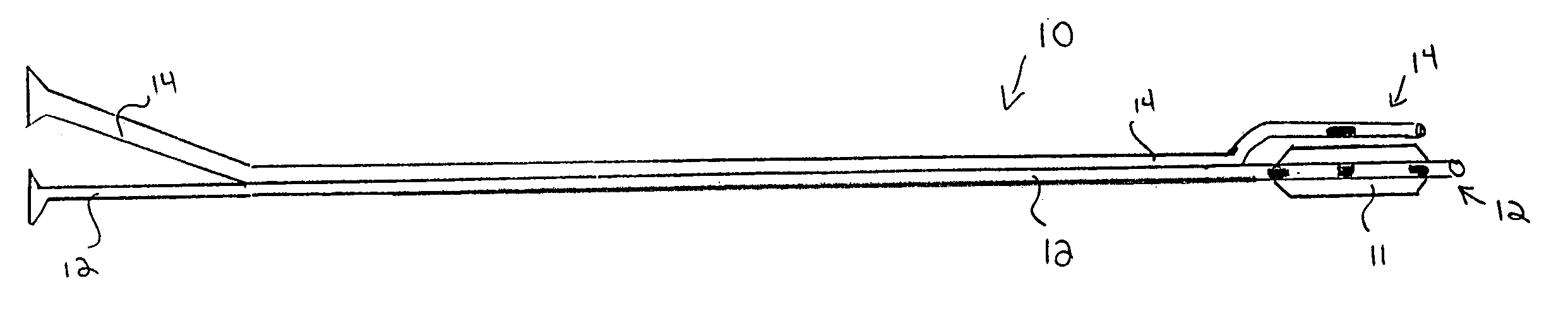
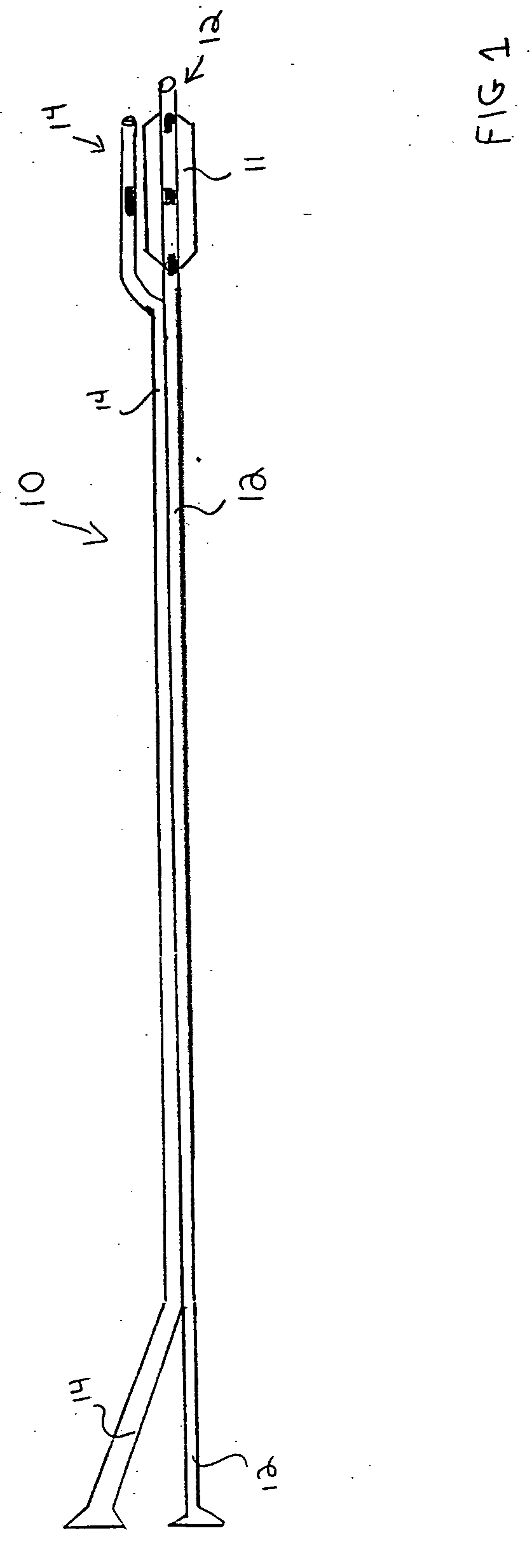
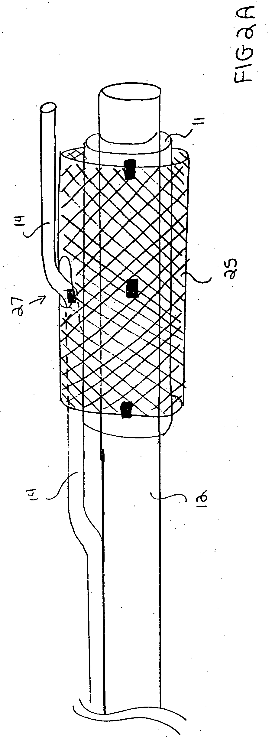
[0036] A novel stent delivery system is provided for accomplishing the preferred methods. Referring to FIGS. 1 to 2B, the present stent delivery system 10 comprises a first catheter 12 having an attached flexible side sheath 14. An inflatable balloon 11 is preferably positioned at the distal end of first catheter 12. As is shown in FIGS. 5 to 6B, first catheter 12 is receivable over a first guidewire 21 and flex...


PUM


Abstract

A method of positioning a main stent at a vessel bifurcation such that a side opening in the main stent is positioned at the ostium of a branch vessel, comprising: positioning a main guidewire in the main vessel such that a distal end of the main guidewire extends past the bifurcation; advancing a stent delivery system to a position proximate the bifurcation, the stent delivery system comprising a catheter with a flexible side sheath attached thereto, wherein the catheter is received over the main guidewire, and wherein the main stent is positioned over the catheter with the flexible side sheath positioned to pass through the interior of the main stent and out of the side opening in the main stent; advancing a branch guidewire through the flexible side sheath attached to the catheter and into the branch vessel; and subsequently, advancing the catheter over the main guidewire while advancing the flexible side sheath over the branch guidewire while viewing relative movement of a marker positioned on the flexible side sheath with respect to at least one marker positioned on the catheter, wherein the relative movement indicates that a portion of the flexible side sheath adjacent the side opening in the main stent is advancing into the ostium of the branch vessel, thereby indicating the position of the side opening of the main stent with respect to the ostium of the branch vessel.

Description

CROSS-REFERENCES TO RELATED APPLICATIONS [0001] The present invention is related to co-pending U.S. patent application Ser. No. 08 / 744,022 filed Nov. 4, 1996, now abandoned; Ser. No. 08 / 935,383 filed Sep. 23, 1997; Ser. No. 09 / 007,265 filed Jan. 14, 1998; and 60 / 088,301 filed Jun. 5, 1998; PCT Patent Application No. PCT / US99 / 00835 filed Jan. 14, 1999; and U.S. patent application Ser. No. 09 / 325,996 filed Jun. 4, 1999, the disclosures of which are incorporated herein by reference in their entirety for all purposes.TECHNICAL FIELD [0002] The present invention relates to catheter systems for delivering stents. BACKGROUND OF THE INVENTION [0003] A type of endoprosthesis device, commonly referred to as a stent, may be placed or implanted within a vein, artery or other tubular body organ for treating occlusions, stenoses, or aneurysms of a vessel by reinforcing the wall of the vessel or by expanding the vessel. Stents have been used to treat dissections in blood vessel walls caused by bal...

Claims


Application Information

Patent Timeline
IPC IPC(8): A61B5/05A61F2/00A61F2/06A61F2/84A61F11/00
CPCA61F2/856A61F2/954A61F2250/0097A61F2250/006A61F2/958Y10S623/903
Inventor VARDI, GIL M.DAVIDSON, CHARLES J.WILLIAMS, ERIC
Owner BOSTON SCI SCIMED INC
Why Eureka
Try Eureka