
High-precision stamping die assembly with safety protection function

A technology for safety protection and stamping dies, applied in the field of stamping dies, can solve the problems of unbalanced stamping force, complexity of operation, hidden dangers of stamping dies, etc., and achieve the effect of easy and reliable punching and wide adaptability.

Active Publication Date: 2015-12-09
深圳市佳合丰科技有限公司
View PDF8 Cites 9 Cited by
  • Summary
  • Abstract
  • Description
  • Claims
  • Application Information

AI Technical Summary

Problems solved by technology

[0002] When stamping flat materials, we found that the existing stamping dies have potential safety hazards. When the punch in the upper die assembly moves towards the die in the lower die assembly, it cannot sense whether there is an object other than the workpiece. , so it is very easy to cause damage to human body parts that have entered by mistake or have not completely left from the vicinity of the workpiece; to avoid this situation, the current design idea is to prevent the start switch from being touched by mistake or set two buttons to be pressed at the same time to start Structure; this structure brings the complexity of the operation, and because it is not directly determined whether there is a foreign body in the stamping area, there is still a safety hazard;
[0003] In the stamping die assembly we currently use, the movement of the upper die assembly relative to the lower die assembly is driven by a cylinder or a motor; the motor drive has high precision but low efficiency; the cylinder drive has high efficiency, but there is an unbalanced stamping force. Some container structures that require punching and holding, that is, do not need to punch the workpiece through the hole, but stamp the flat workpiece into a cup shape, require a gradual stretching and deformation process, and the current cylinder power will have the defect of poor precision

Method used


Image

  • High-precision stamping die assembly with safety protection function
  • High-precision stamping die assembly with safety protection function
  • High-precision stamping die assembly with safety protection function

Examples


specific Embodiment approach

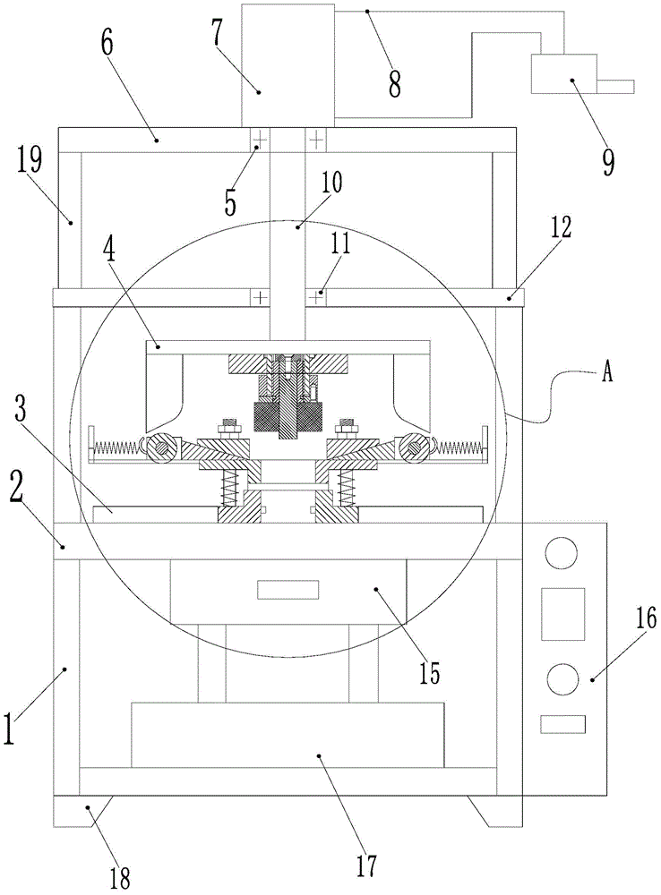
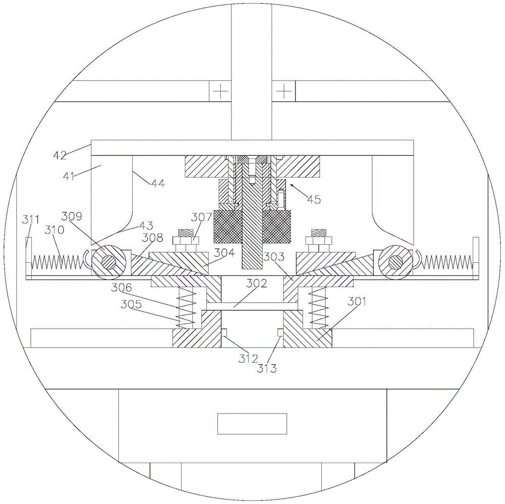
[0035] Such as Figure 1~4As shown, it shows a specific embodiment of the present invention, as shown in the figure, the high-precision stamping die assembly with safety protection function of the present invention includes a frame and an upper die assembly 4 and a lower die installed on the frame Component 3; the upper mold assembly and the lower mold assembly are arranged opposite to each other, and the upper mold assembly is located above the lower mold assembly; the upper mold assembly is driven up and down by the hydraulic cylinder assembly; the upper mold assembly and the lower mold assembly A punch 4511 and a die that cooperate with each other are respectively arranged on the component;

[0036] As shown in the figure, the hydraulic cylinder assembly includes a hydraulic cylinder block 7 and a piston rod 10, and the bottom end of the piston rod is connected to the lifting plate 42 of the upper mold assembly 4;

[0037] Such as Figure 4 As shown, the upper mold assemb...


PUM


Abstract

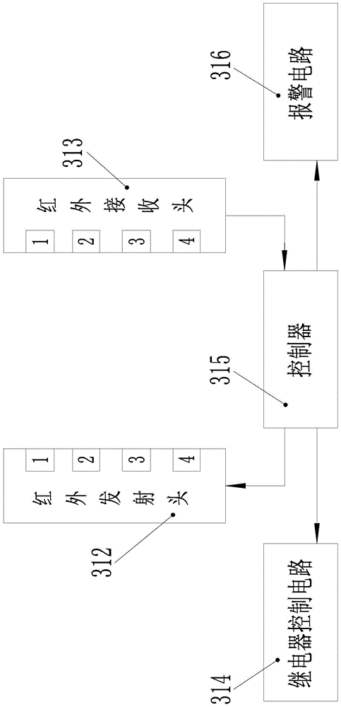
The invention discloses a high-precision stamping die assembly with a safety protection function. The high-precision stamping die assembly has reliable hydraulic power and has the reliable safety protection function, and meanwhile a male die can be replaced. The high-precision stamping die assembly comprises a rack, an upper die assembly and a lower die assembly, wherein the upper die assembly and the lower die assembly are arranged on the rack and opposite to each other, and the upper die assembly is located above the lower die assembly. The upper die assembly is driven through a hydraulic oil cylinder assembly to ascend and descend. The upper die assembly and the lower die assembly are provided with the male die and a female die which are matched with each other respectively. The upper die assembly further comprises a male die assembly fixed to the bottom face of a lifting board. The male die assembly comprises a fixing board fixedly connected to the bottom face of the lifting board. The fixing board is provided with a male die fixing base connection hole. A male die fixing base is connected into the male die fixing base connection hole. An axial connection hole is formed in the male die fixing base. A male die mechanism is connected into the axial connection hole in a matched manner. The side wall of the female die of the lower die assembly is provided with an infrared transmitting head and an infrared receiving head.

Description

technical field [0001] The invention relates to a stamping die, in particular to a high-precision stamping die. Background technique [0002] When stamping flat materials, we found that the existing stamping dies have potential safety hazards. When the punch in the upper die assembly moves towards the die in the lower die assembly, it cannot sense whether there is an object other than the workpiece. , so it is very easy to cause damage to human body parts that have entered by mistake or have not completely left from the vicinity of the workpiece; to avoid this situation, the current design idea is to prevent the start switch from being touched by mistake or set two buttons to be pressed at the same time to start Structure; this structure brings the complexity of the operation, and because it is not directly determined whether there is a foreign body in the stamping area, there is still a safety hazard; [0003] In the stamping die assembly we currently use, the movement of ...

Claims


Application Information

Patent Timeline
IPC IPC(8): B21D37/10B21D55/00
Inventor 吴晓明吴海燕龙梅朱建武罗红梅石国军
Owner 深圳市佳合丰科技有限公司
Learn More