
Piezoelectric array spray head and spraying equipment including the same

A piezoelectric array and nozzle technology, applied in the field of piezoelectric ceramics, can solve the problems of low physical resolution, narrow application range, and inability to adjust, and achieve the effect of high physical resolution, wide application range, and simple structure

Active Publication Date: 2017-01-18
PAIHE SCI & TECH HLDG CO LTD BEIJING +1
View PDF8 Cites 1 Cited by
  • Summary
  • Abstract
  • Description
  • Claims
  • Application Information

AI Technical Summary

Problems solved by technology

[0005] 1. The physical resolution is low; the piezoelectric film is arranged at intervals along the direction of its own width, so that the distance between adjacent nozzles must be greater than the width of the piezoelectric film, because the output force of the piezoelectric film must reach a certain level to make the vibration The plate is deformed, so the width of the piezoelectric film cannot be too narrow, so that the distance between adjacent nozzles cannot be very close, and the physical resolution is not high
[0006] 2. The physical resolution is not adjustable, and the scope of application is narrow; after the ink chamber is processed, the physical resolution of the inkjet head is fixed and cannot be adjusted, and cannot adapt to the work requirements of different occasions (such as inkjet printing, dispensing , spraying glaze or spraying electrode slurry and other different occasions), the scope of application is narrow

Method used


Image

  • Piezoelectric array spray head and spraying equipment including the same
  • Piezoelectric array spray head and spraying equipment including the same
  • Piezoelectric array spray head and spraying equipment including the same

Examples


Embodiment Construction

[0036] In order to make the technical problems, technical solutions and advantages to be solved by the present invention clearer, a detailed description will be given below in conjunction with the drawings and specific embodiments.

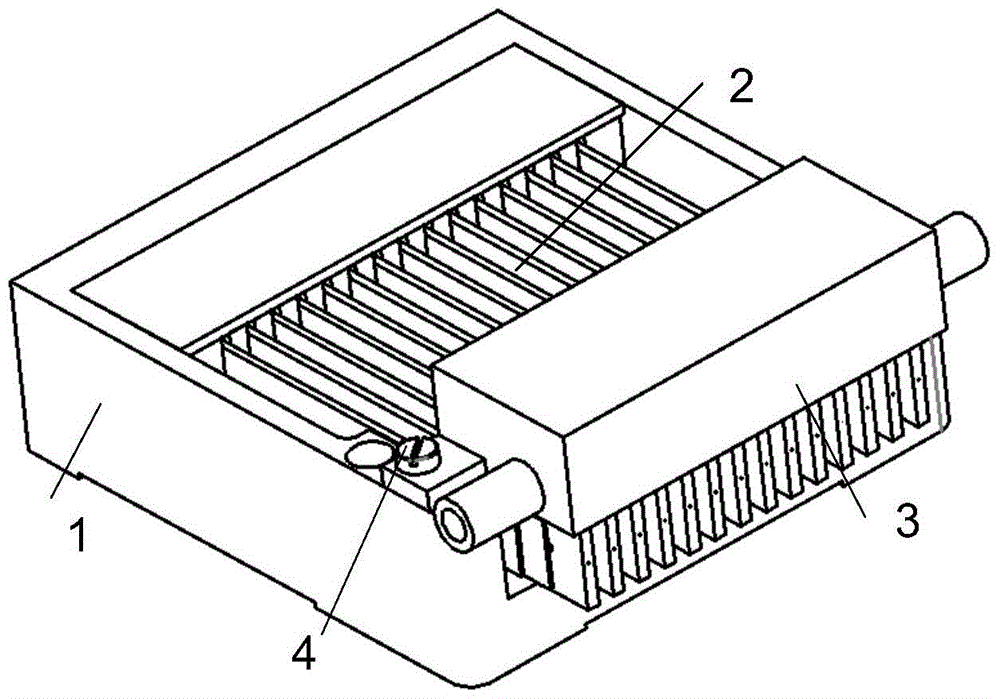
[0037] In one aspect, the present invention provides a piezoelectric array nozzle, such as Figure 3 to Figure 7 As shown, the nozzle power part 2 and the nozzle ink part 3 are included, and the nozzle ink part 3 includes a plurality of sheet-shaped and parallel inkjet chambers 32;

[0038] Each ink jet cavity 32 is provided with an ink inlet 324, an ink outlet 325, and a nozzle 326. The nozzle 326 is located on an end surface of the ink jet cavity 32 parallel to the thickness direction. The ink jet cavity 32 is perpendicular to the thickness direction. The two side walls are flexible side walls 322;

[0039] The nozzle power part 2 adopts a piezoelectric ceramic cantilever beam 23, one end of the piezoelectric ceramic cantilever beam 23 is fixed, and t...


PUM


Abstract

The invention discloses a piezoelectric array nozzle and spraying equipment comprising the same, and belongs to the field of piezoelectric ceramics. The nozzle comprises a nozzle power part an a nozzle ink part, wherein the nozzle ink part comprises a plurality of sheet-shaped parallel ink-spraying cavities. Each ink-spraying cavity is provided with an ink inlet, an ink outlet, and a spraying nozzle, wherein the spraying nozzle is located on an end face, parallel to the thickness direction, of the ink-spraying cavity. Two side walls, perpendicular to the thickness direction, of each ink-spraying cavity are flexible side walls. The nozzle power part employs a piezoelectric ceramic cantilever beam, wherein one end of the piezoelectric ceramic cantilever beam is fixed and the other end of the piezoelectric ceramic cantilever beam contacts with and drives the flexible side walls. Compared with the prior art, the nozzle provided by the invention is high in physical resolution, and the physical resolution can be adjusted. The nozzle is wide in application range, is simple in structure, and is convenient for maintenance.

Description

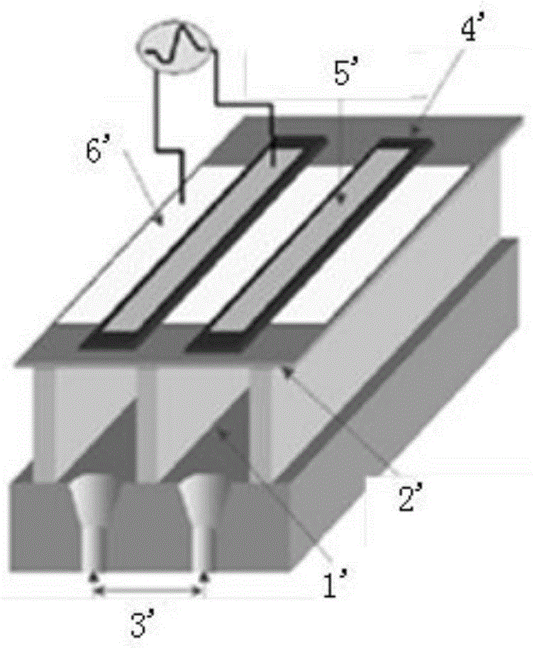
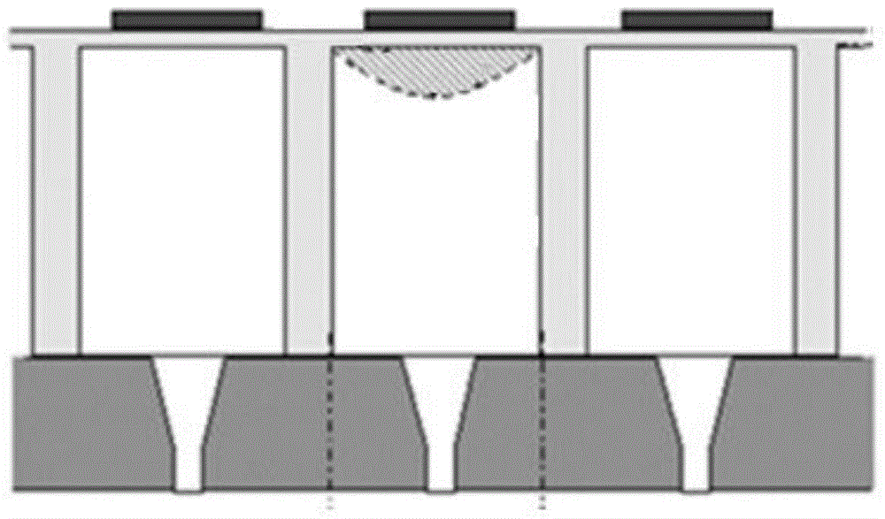
Technical field [0001] The invention relates to the field of piezoelectric ceramics, in particular to a piezoelectric array spray head and a spraying equipment including the spray head. Background technique [0002] The nozzle is the core of the inkjet printer or dispenser, the highest cost, and the highest technical component. The domestic research and development to manufacturing are blank, and they are completely dependent on imports. [0003] Take Epson inkjet head as an example, such as figure 1 with figure 2 As shown, it includes ink chamber 1', vibration plate 2', nozzle 3', piezoelectric film 4', and upper electrode 5'and lower electrode 6'connecting the upper and lower surfaces of piezoelectric film 4'. When pressure is applied When the electric film 4'is energized, it deforms and squeezes the vibrating plate 2', causing the vibrating plate 2'to generate displacement into the ink chamber 1', causing the ink to be ejected from the nozzle 3'. [0004] However, this inkjet he...

Claims


Application Information

Patent Timeline
Patent Type & Authority Patents(China)
IPC IPC(8): B41J2/14B41J2/01
Inventor 祝聪张淑兰
Owner PAIHE SCI & TECH HLDG CO LTD BEIJING
Learn More