
Magnetron radiating element, magnetron and microwave cooking device

A heat dissipation element and cooking device technology, which is applied in the direction of electrical components, discharge tubes, and time-of-flight electronic tubes, can solve problems such as insufficient heat dissipation of the sleeve, loss of heat dissipation effect of the heat dissipation plate, and limited coaxiality, etc.

Inactive Publication Date: 2017-12-29
GUANGDONG WITOL VACUUM ELECTRONICS MFR
View PDF5 Cites 1 Cited by
  • Summary
  • Abstract
  • Description
  • Claims
  • Application Information

AI Technical Summary

Problems solved by technology

[0007] The above scheme can simplify the assembly steps between the heat dissipation component and the black ball component during assembly, but the processing of the heat dissipation component itself becomes more complicated, and more importantly, the sleeve needs to pass through each layer of heat dissipation plate and connect with the heat dissipation Each anode hole on the plate is in close contact with
If the anode hole is processed before the metal plate is bent, the coaxiality of the anode hole on the multi-layer heat sink is limited by the bending process and the error of punching, and these differences may cause the sleeve and the heat sink Poor contact leads to insufficient heat dissipation on the sleeve; if the anode hole is processed after the metal plate is bent, the process of opening the anode hole itself will change the size of the gap between the cooling plates along the axis of the sleeve (The force direction of the punching is the axial direction of the sleeve, which will inevitably cause the metal plate to deform in this direction), and the gap between adjacent cooling plates is the air duct for heat exchange, so this method will also The gap between the affected parts of the heat sink is too small and the heat dissipation effect is lost

Method used


Image

  • Magnetron radiating element, magnetron and microwave cooking device
  • Magnetron radiating element, magnetron and microwave cooking device
  • Magnetron radiating element, magnetron and microwave cooking device

Examples


Embodiment 1

[0042] Embodiment 1: A magnetron heat dissipation element with better combination of processing simplicity and heat dissipation effect.

[0043] like Figure 4 and Figure 6 As shown in , the magnetron cooling element according to a preferred embodiment of the present invention includes a central cooling body 105 . exist Figure 4 to Figure 7 In the first specific embodiment of the magnetron heat dissipation element shown in , the central heat dissipation body 105 has a rectangular cross-section (such as Figure 6 As shown in , including a square cross-section), a cylindrical central assembly hole that is coated and bonded to the outer wall of the anode cylinder is formed on the central radiator 105, and the inner hole wall of the central assembly hole is the contact surface 104, The contact surface 104 is attached to the outer wall of the anode cylinder to conduct heat conduction therewith.

[0044] Along the axial direction of the anode cylinder, the height of the centra...

Embodiment 2

[0054] Embodiment 2: A heat dissipation element for a magnetron with priority given to the heat dissipation effect.

[0055] like Figure 9-11 As shown in , the difference from the previous embodiment is that, along the radial direction of the anode cylinder, the central radiator 105 has a circular cross-section, so that the thickness of the central radiator 105 is uniform, close to the thin-walled sleeve structure (compared to In embodiment 1, the center radiator 105 is thicker at the four corners of the rectangular cross-section and thinner near the midpoint of the side length), this structure is more conducive to the heat conduction from the outer wall of the anode cylinder to the center radiator 105 Dissipate through the cooling fins. Moreover, the formed central air channel 102 is an annular band structure, and when the cooling air flows through the central air channel 102 , it is more fully mixed with the hot air in the central air channel 102 , and the heat dissipation...

Embodiment 3

[0058] Embodiment 3: A heat dissipation element for a magnetron that gives priority to processing simplicity.

[0059] like Figure 12 to Figure 14 As shown, the only difference between it and Embodiment 1 is that the second middle air passage is omitted, so that the central radiator 105 only has the first middle air passage on both sides of the cooling air blowing direction.

[0060] As described in Example 1, the second middle air channel is an integral extrusion-molded structure with rear row of cutters. Canceling the second middle air channel can correspondingly save the process of material removal, and only need to drill the center after extrusion molding. Only holes are needed, and the manufacturing process and material costs are reduced.

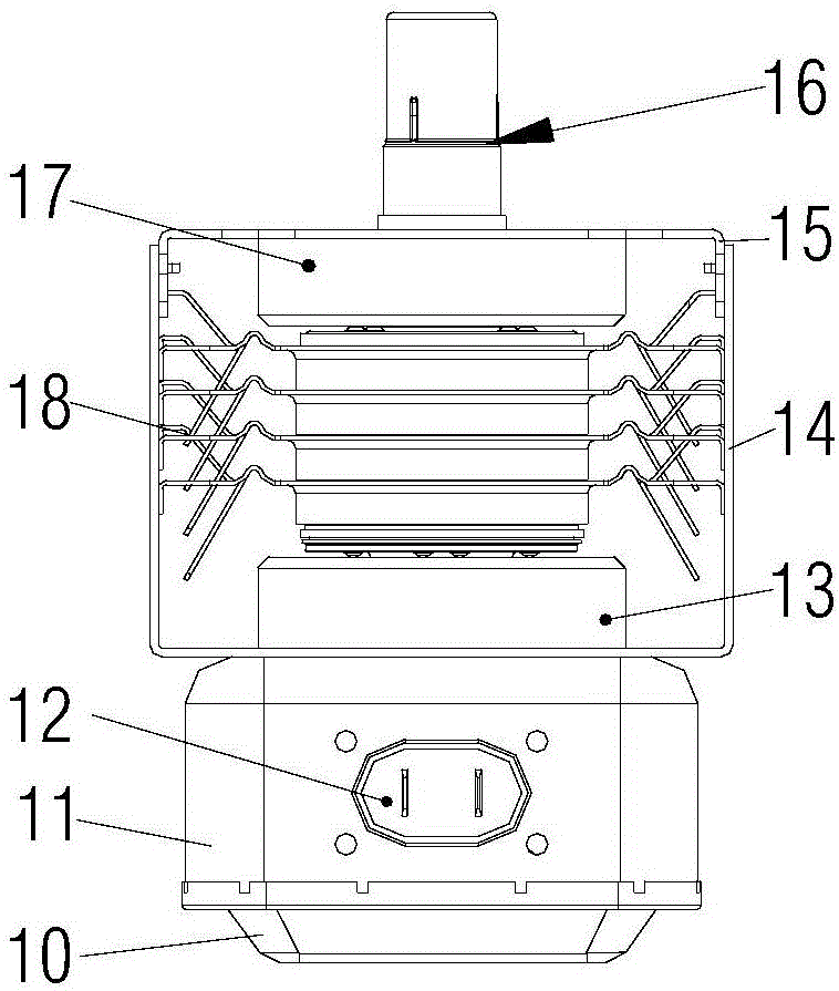
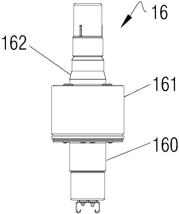
[0061] In addition, the present invention also provides a magnetron ( Figure 8 It can represent the installation structure of the magnetron in the first two embodiments, and the structure of the magnetron formed by the installation...


PUM


Abstract

The invention relates to the technical field of magnetron structure, and discloses a magnetron radiating element, a magnetron and a microwave cooking device. The magnetron radiating element comprises a center radiating body (105) and a plurality of radiating fins integrally formed together with the center radiating body (105) and extending outwardly at intervals. Air ducts are correspondingly formed between adjacent radiating fins. A center assembly hole used to coat and fit the outer wall of an anode cylinder (161) is formed in the center radiating body (105). According to the magnetron radiating structure, the efficiency of heat transfer between the anode cylinder and a radiating component and inside the radiating component is improved while the structure of the radiating component and the installation structure of the radiating component and a black ball component are simplified as much as possible, and therefore, the radiating efficiency of the magnetron radiating structure is improved.

Description

technical field [0001] The invention relates to the technical field of magnetron structure, in particular to a magnetron cooling element. Correspondingly, the present invention also relates to a magnetron and a microwave cooking device using the magnetron cooling element. Background technique [0002] Magnetron is a kind of microwave electron tube, which is a reentrant resonant cross-field oscillator, usually used as a high-power microwave generator. Due to the working characteristics of the magnetron itself, even under normal working conditions, the resonant cavity of the magnetron generates a large amount of heat. Therefore, proper cooling is an important condition to ensure the normal operation of the magnetron. When a high-power magnetron is used, its anode needs to be water-cooled to achieve the purpose of temperature control. [0003] For the magnetron used for heating in microwave ovens, because of its low power, forced air cooling is often used for cooling. Specif...

Claims


Application Information

Patent Timeline
IPC IPC(8): H01J23/00
CPCH01J23/005
Inventor 陈文
Owner GUANGDONG WITOL VACUUM ELECTRONICS MFR
Learn More