A flow-limiting hermetic exhaust valve for aerostats and its position-limiting control method

A technology for exhaust valves and aerostats, which is applied in the field of aviation aerostats, can solve the problems of high assembly accuracy, no pre-tightening force on the valve cover, and inability to ensure airtightness, etc., so as to improve product reliability and increase Good air tightness and product consistency

Inactive Publication Date: 2017-06-16
ACAD OF OPTO ELECTRONICS CHINESE ACAD OF SCI
View PDF5 Cites 0 Cited by
  • Summary
  • Abstract
  • Description
  • Claims
  • Application Information

AI Technical Summary

Problems solved by technology

[0008] In order to solve the problem that the lower limit element of the existing exhaust valve used for the aerostat needs to be manually adjusted, the assembly accuracy is too high, and there is no pre-tightening force when the valve cover is closed, and sufficient airtightness cannot be guaranteed.

Method used


Image

  • A flow-limiting hermetic exhaust valve for aerostats and its position-limiting control method
  • A flow-limiting hermetic exhaust valve for aerostats and its position-limiting control method
  • A flow-limiting hermetic exhaust valve for aerostats and its position-limiting control method

Examples


Embodiment 1

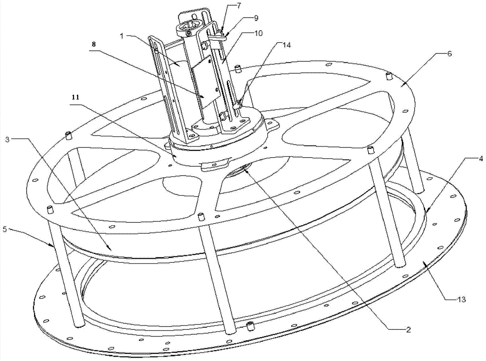
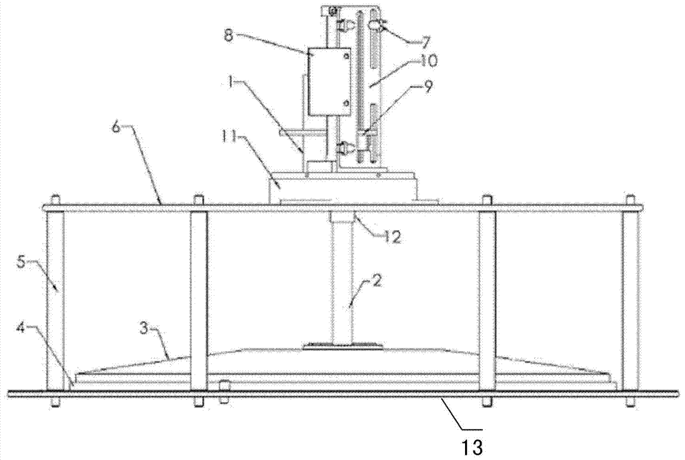
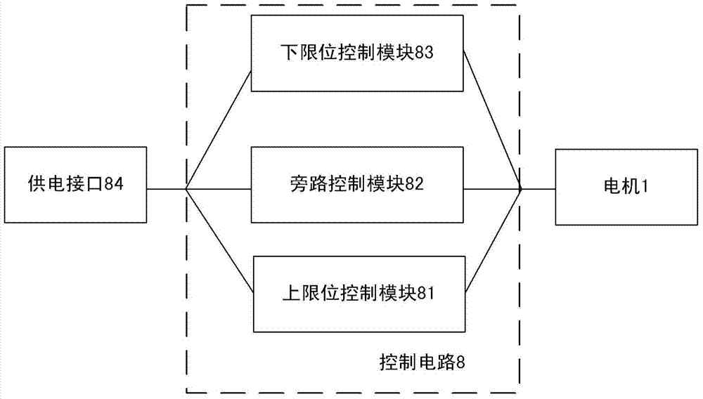
[0021] Embodiment 1: Ideally, there should be a certain pre-tightening force after the valve cover 3 is closed to ensure the airtightness of the exhaust valve, which is especially important for the helium exhaust valve of the main air bag of the aerostat. The valve cover 3 covers the sealing ring 4 and the valve port of the valve body 13; the control circuit 8 is connected to the motor 1, and is used to control the rotation of the motor 1 and limit the current of the motor 1 to automatically cut off the power supply of the motor 1; the motor 1 is connected to the valve cover 3, It is used to control the lifting and moving down of the valve cover 3 along the lead screw; the upper limit element 7 is connected to the control circuit 8; the stop block 9 is fixedly connected to the lead screw 2; when the motor 1 rotates, the stop block 9 moves up and down along the lead screw 2 , the gear block 9 is in contact with the upper limit element 7, the upper limit element 7 cuts off the co...

Embodiment 2

[0022] Embodiment 2: The upper limit of the opening of the exhaust valve only determines the degree of opening of the valve cover 3, and a slight installation error does not affect the performance of the exhaust valve. Therefore, the current control of the lower limit of the closing of the valve cover 3 is mainly considered here. After the bonnet 3 is in contact with the sealing ring 4, the current increased due to the blocked rotation of the motor 1, and after a certain level, the power is cut off. The magnitude of the current can determine the pretightening force of the bonnet 3 closing, so through the circuit design, It can be guaranteed that all the valve covers 3 produced can be closed in place, and there is a consistent pretightening force after the valve covers 3 are closed, which is beneficial to enhance the airtightness of the exhaust valve. Thus, the present invention arranges a circle of screw holes on the outer circle of the valve body 13, and relies on the screw ho...

Embodiment 3

[0023] Embodiment 3: A plurality of columns 5 are respectively located between the base 6 and the valve body 13 and the two are connected into one body, and the plurality of columns 5 are used to support the base 6 and the valve body 13; the screw 2 is connected through the screw 2 The screw holes arranged on the flange structure of the lower end face of the valve are fixedly connected with the valve cover 3, and the lead screw 2 is used for opening and closing the valve cover to leave and cover the valve port. The upper end surface of the lead screw 2 has a threaded hole.


PUM


Abstract

The present invention is a flow-limiting airtight exhaust valve for aerostats and its position-limiting control method. The exhaust valve includes: a motor, a lead screw, a valve cover, a sealing ring, a column, a base, and an upper limit position. Components, control circuit, stop block, bracket, base, driven wheel and valve body, the valve cover covers the sealing ring and the valve port of the valve body; the control circuit is connected with the motor; the motor is connected with the valve cover for controlling the valve cover along the The lead screw is lifted and moved down; the upper limit element is connected with the control circuit; the stop block is fixedly connected with the lead screw; when the motor rotates, the stop block moves up and down along the lead screw, the stop block contacts the upper limit element, and the upper limit element is cut off The control circuit, the motor stops, and the valve cover is in the maximum open state; when the motor reverses and the stop block moves downward, the contact between the valve cover and the sealing ring reaches the preset compression state, and the preset pressure is maintained between the valve cover and the sealing ring. The tightening force, the current limiting of the control circuit cuts off the power supply of the motor, automatically closes the valve cover tightly and is in a sealed closed state.

Description

technical field [0001] The invention belongs to the technical field of aviation aerostats, and relates to a flow-limiting airtight exhaust valve for aerostats. Background technique [0002] An aerostat is a lighter-than-air aircraft. The capsule body is made of polymer composite material, and the airbag is filled with a buoyant gas with a density lower than that of air. The density difference between the inside and outside of the airbag provides static buoyancy, thereby obtaining a lift that can overcome its own weight. [0003] The aerostat is an inflatable flexible body, which must be controlled by pressure so that the pressure difference between the inside and outside remains within a certain range during the entire flight, thereby maintaining the external shape of the entire aerostat. During the ascent, as the flight altitude increases, the density of the outside air and the atmospheric pressure gradually decrease, and the volume of the buoyant gas in the aerostat expan...

Claims


Application Information

Patent Timeline
Patent Type & Authority Patents(China)
IPC IPC(8): B64B1/62
Inventor 黄宛宁何小辉
Owner ACAD OF OPTO ELECTRONICS CHINESE ACAD OF SCI
Why Eureka
Try Eureka