A multifunctional vibrating device

A multi-functional and equipment technology, applied in the direction of earth mover/shovel, construction, etc., can solve the problems of transportation and rapid construction, the fracture of bucket teeth and knife row welds, and the inability to adapt to national defense construction, etc., to achieve convenient The effect of quick start of construction, low working noise and strong self-protection function

Active Publication Date: 2017-11-14
SHANGHAI UNIV OF ENG SCI
View PDF5 Cites 0 Cited by
  • Summary
  • Abstract
  • Description
  • Claims
  • Application Information

AI Technical Summary

Problems solved by technology

Vibration technology has been used in a large number of civil equipment such as excavators, pile drivers, breakers, and road rollers, but its single function and large number cannot adapt to national defense construction under militarized conditions, and there are serious hidden dangers especially in war emergencies
[0003] The Chinese patent with the application number 201110081337.6 discloses a high-frequency breaker, which completely adopts the excitation technology to break rocks. At the same time, the welding of bucket teeth and blades often breaks and damages during work, and maintenance is extremely difficult, so it is not suitable for military applications
[0004] Other construction machinery, including piling machines, road rollers, and other equipment are also single-function equipment, and the equipment is bulky and cannot be flexibly maneuvered. It is very difficult to transport and quickly put into construction during wartime. It is not suitable for the construction of temporary roads on the battlefield, military airports, and other fortifications Work

Method used


Image

  • A multifunctional vibrating device
  • A multifunctional vibrating device
  • A multifunctional vibrating device

Examples


Embodiment 1

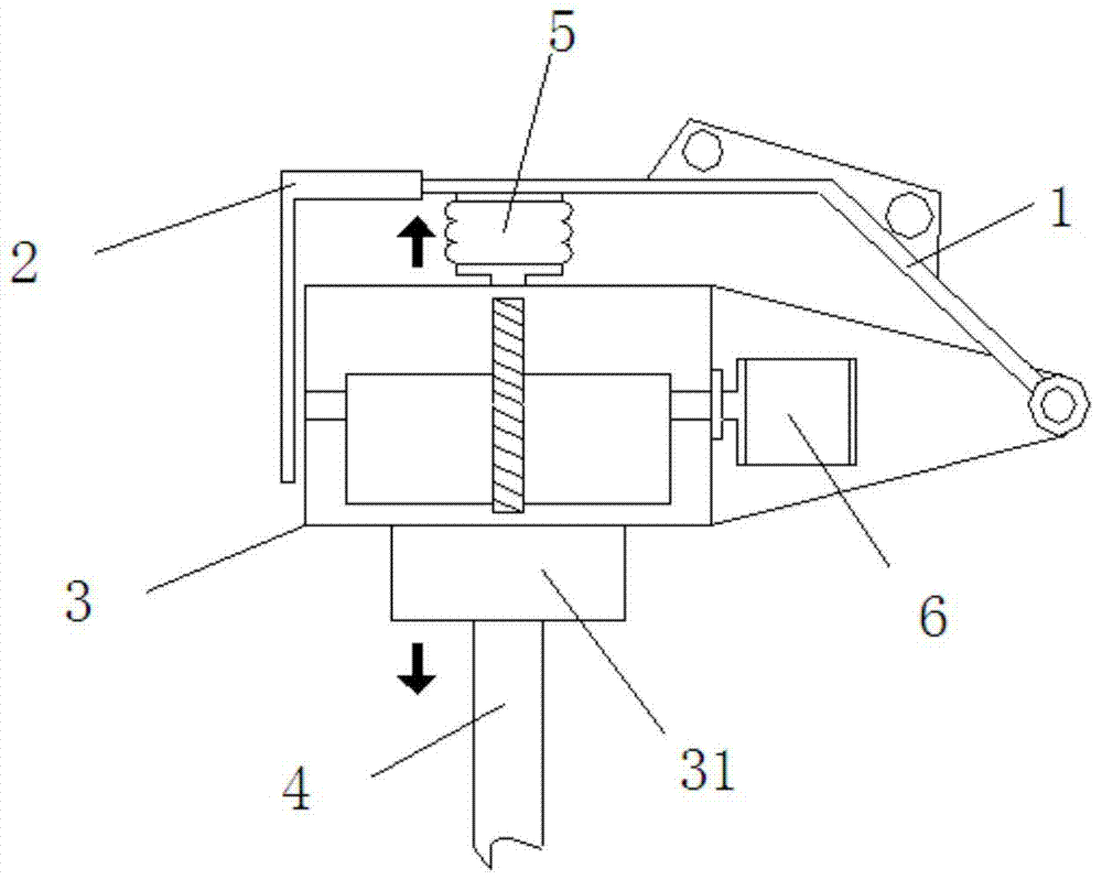
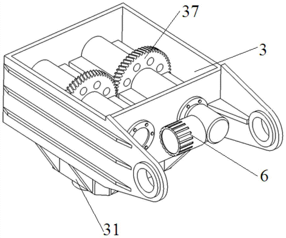
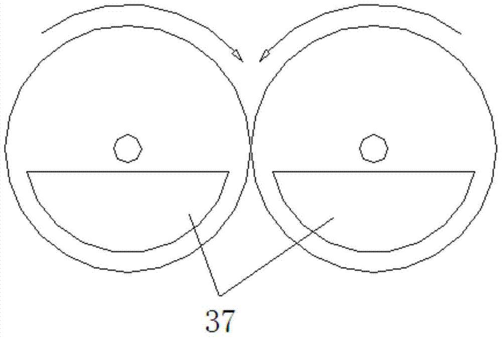
[0034] A multifunctional vibration device, such as figure 1 As shown, it includes frame 1, functional baffle 2, vibration box 3, work piece 4, nitrogen gas spring 5 and hydraulic motor 6, frame 1 covers the top of vibration box 3, and is hinged with vibration box 3, and frame 1 is used for In connection with the excavator, the nitrogen spring 5 is set between the top of the vibration box 3 and the frame 1, the work piece 4 is connected to the bottom of the vibration box 3, and the hydraulic motor 6 is connected to the side of the vibration box 3 to drive the vibration box 3 to the machine Frame 1 generates high-frequency vibration, and relies on nitrogen spring 5 for shock absorption, and the generated vibration drives work piece 4 to vibrate. The functional baffle 2 is fixedly connected to the front end of the frame 1 . This functional baffle plate 2 can also carry out work such as pavement tiling and gravel cleaning as required while protecting the normal operation of the v...

Embodiment 2

[0039] Such as Figure 7 As shown, the difference from Embodiment 1 is that in this embodiment, the work piece 4 is a flat drill rod 43, and the flat drill rod 43 can break targets such as concrete pavements or rocks.

Embodiment 3

[0041] Such as Figure 8 As shown, the difference from Embodiment 1 is that in this embodiment, the work piece 4 is a pointed drill rod 44, and the pointed drill rod 44 can break targets such as concrete pavements or rocks.


PUM


Abstract

The invention relates to a multifunctional vibration device. The multifunctional vibration device comprises a machine frame, a vibration box, a workpiece, a nitrogen spring and a hydraulic motor. The top end of the vibration box is covered with the machine frame. The machine frame is hinged to the vibration box and used for being connected with an excavator. The nitrogen spring is arranged between the top end of the vibration box and the machine frame. The workpiece is connected to the bottom end of the vibration box. The hydraulic motor is connected to the lateral side of the vibration box. A pair of meshed eccentric gears are arranged in the vibration box. At least one eccentric gear is driven by the hydraulic motor. The hydraulic motor makes the eccentric gears rotate at a high speed, force in the horizontal direction is mutually counteracted, excitation force is generated in the vertical direction, and therefore vibration is generated. Damping is achieved through the nitrogen spring, and generated vibration drives the workpiece to vibrate. Compared with the prior art, the multifunctional vibration device has the beneficial effects that multiple functions are achieved, cost is low, operation is convenient, and the application range is wide.

Description

technical field [0001] The invention relates to the field of engineering machinery, in particular to a multifunctional vibrating device. Background technique [0002] At present, vibration technology has been used in construction machinery, but it has not been effectively developed. A large number of civilian equipment such as excavators, pile drivers, breakers, and road rollers have used vibration technology, but their single function and large number cannot adapt to national defense construction under militarized conditions, and there are serious hidden dangers especially in war emergencies. [0003] The Chinese patent with the application number 201110081337.6 discloses a high-frequency breaker, which completely adopts the excitation technology to break rocks. At the same time, the welding joints of bucket teeth and blades are often broken and damaged during work, and maintenance is extremely difficult, so it is not suitable for military applications. [0004] Other con...

Claims


Application Information

Patent Timeline
Patent Type & Authority Patents(China)
IPC IPC(8): E02F5/30
Inventor 胡凯俊杨国平
Owner SHANGHAI UNIV OF ENG SCI
Why Eureka
Try Eureka