
Compressor

A technology of a compressor and a compression mechanism, applied in the field of compressors, can solve the problems affecting the energy efficiency and high power of the compressor, and achieve the effects of improving adaptability, improving performance, improving heating capacity and energy efficiency

Active Publication Date: 2015-12-09
GUANGDONG MEIZHI COMPRESSOR +1
View PDF6 Cites 4 Cited by
  • Summary
  • Abstract
  • Description
  • Claims
  • Application Information

AI Technical Summary

Problems solved by technology

However, when the compressor is running in single-stage mode, its power will be higher than that of ordinary compressors due to the extra piston running, which will affect the final energy efficiency of the compressor

Method used


Image

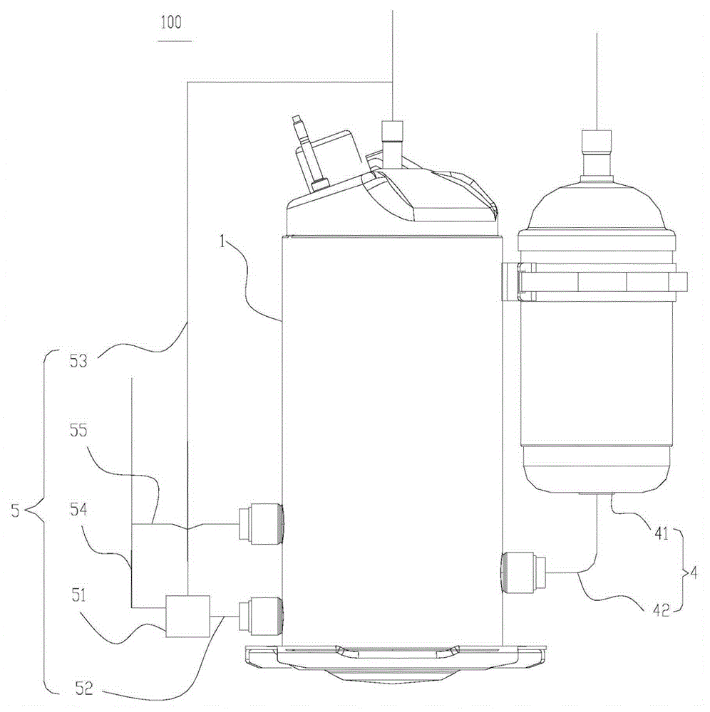
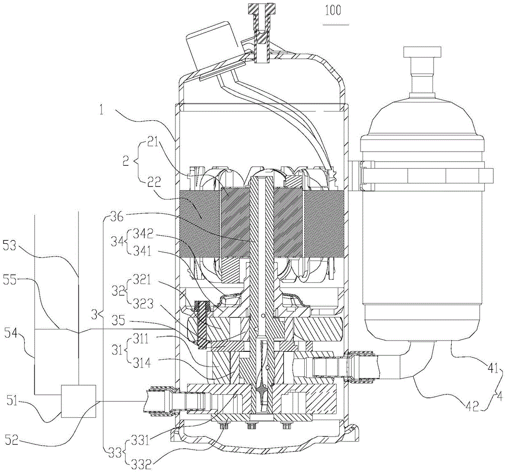
  • Compressor
  • Compressor
  • Compressor

Examples


Embodiment 1

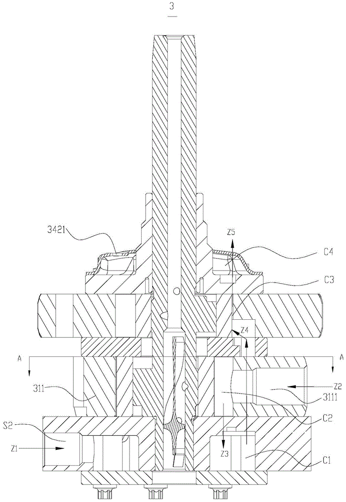
[0087] refer to Figure 4 and Figure 5 The injection port S5 is formed on the first cylinder 311, and an injection channel S4 communicating with the injection port S5 is further formed on the first cylinder 311, and the injection valve 6 is a valve assembly arranged on the injection channel S4. refer to image 3 , the injection channel S4 can penetrate the first cylinder 311 along the radial direction of the first cylinder 311, and the outer end of the injection channel S4 penetrates the outer peripheral surface of the first cylinder 311, and the inner end of the injection channel S4 penetrates to the first compression chamber C2, the valve The assembly may include an injection valve seat, a lift limiter 61 and a one-way valve plate 62 installed on the injection valve seat, wherein a perforation that does not block the injection channel S4 is formed on the injection valve seat, and the lift limiter 61 It can be fixed on the side of the injection valve seat adjacent to the f...

Embodiment 2

[0091] The injection port S5 is formed on the diaphragm assembly 35 and / or the first bearing assembly 33, the injection port S5 is configured to be opened and closed by the first piston 314 during the rotation of the first piston 314, and the injection valve 6 is the first piston 314. That is to say, the injection port S5 can be opened or closed during the rolling process of the first piston 314 to realize injection or blocking of the second-pressure refrigerant.

[0092] For example in Image 6In an example, the injection port S5 may be formed on the baffle assembly 35 (and / or the first bearing assembly 33) and communicate with the first compression on the first cylinder 311, the baffle assembly 35 (and / or the first bearing assembly 33) is further formed with an injection channel S4, one end of the injection channel S4 communicates with the injection port S5, and the other end of the injection channel S4 penetrates the outer peripheral surface of the partition plate assembly...

Embodiment 3

[0095] refer to Image 6 The baffle assembly 35 and / or the first bearing assembly 33 are formed with the injection port S5 and the injection channel S4 communicating with the injection port S5, that is to say, the injection port S5 and the injection channel S4 can both be formed on the baffle assembly 35 , the injection port S5 and the injection channel S4 can also be formed on the first bearing assembly 33, the injection port S5 and the injection channel S4 can also be formed on the separator assembly 35 and both are formed on the first bearing assembly 33 at the same time, the injection The valve 6 includes a valve assembly arranged on the injection channel S4, wherein the valve assembly is the same as the valve assembly in the first embodiment above, and will not be described in detail here.


PUM


Abstract

The invention discloses a compressor. The compressor comprises an air sucking component, an air supply component, an injection valve, a first-stage compression component, and a second-stage compression component and a first bearing component which are arranged on two axial sides of the first-stage compression component, wherein the first-stage compression component is provided with a first compression cavity; the second-stage compression component is provided with a second compression cavity; the first bearing component is provided with an intermediate cavity which is connected with an air discharging hole of the first compression cavity and an air sucking hole of the second compression cavity respectively; the air sucking component is used for supplying a first pressure refrigerant to the first compression cavity; the air supply component is used for supplying a second pressure refrigerant or a third pressure refrigerant to the intermediate cavity; when the second pressure refrigerant is supplied to the intermediate cavity, the second-stage compression component can work; when the third pressure refrigerant is supplied to the intermediate cavity, the second-stage compression component does not work; the injection valve is used for supplying the second pressure refrigerant to the first compression cavity. Through the compressor, the single-stage operation and the two-stage operation can be switched; and the compressor is high in efficiency during single-stage operation.

Description

technical field [0001] The invention relates to the technical field of compressors, in particular to a compressor. Background technique [0002] It is pointed out in related technologies that the load of the air conditioner changes with the change of the external conditions. When the load of the air conditioner system is heavy, such as ultra-low temperature heating, due to the large specific volume of the refrigerant, the mass flow rate of the compressor suction decreases, in addition to causing the compressor to heat up. In addition to the significant reduction in capacity, due to the decrease in mass flow rate, it is difficult for the compressor to return oil, and the heat taken away by the refrigerant is reduced, which will easily lead to the wear of the compressor pump body and the decline in the reliability of the motor, and make the energy efficiency of the compressor system low. Under working conditions, the use of two-stage jet compression can effectively increase th...

Claims


Application Information

Patent Timeline
Patent Type & Authority Applications(China)
IPC IPC(8): F04C18/356F04C23/00F04C29/12
Inventor 巫华龙
Owner GUANGDONG MEIZHI COMPRESSOR
Learn More