Rotating shaft device and electronic device

A technology of rotating shaft device and electronic equipment, which is applied in the direction of pivot connection, etc., and can solve the problems of easy oil leakage and powder generation

Active Publication Date: 2015-12-09
LENOVO (BEIJING) LTD
View PDF6 Cites 4 Cited by
  • Summary
  • Abstract
  • Description
  • Claims
  • Application Information

AI Technical Summary

Problems solved by technology

[0006] The embodiment of the present application provides a rotating shaft device and electronic equipment, which solves the technical problems of easy oil leakage and powder generation in the rotating shaft connecting the main bodies of the electronic equipment in the prior art, and provides a rotating shaft device for connecting the main bodies of the electronic equipment. The new type of rotating shaft realizes the technical effect of no oil leakage of the rotating shaft and no powder generation

Method used


Image

  • Rotating shaft device and electronic device
  • Rotating shaft device and electronic device
  • Rotating shaft device and electronic device

Examples


Embodiment 1

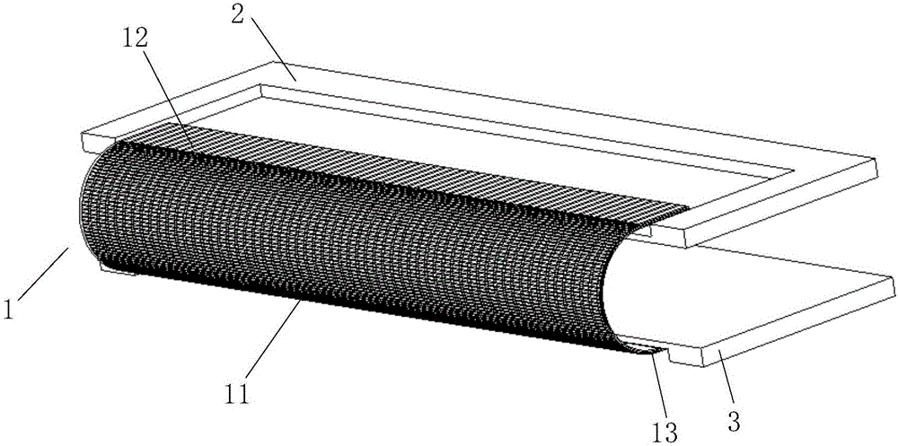
[0048] Please refer to figure 1 , a rotating shaft device provided in Embodiment 1 of the present application, including: a torque generating structure 1, the torque generating structure 1 includes a torque generating body 11, and a first connecting structure 12 and a second connecting structure 12 arranged at opposite ends of the torque generating body 11. The connection structure 13, the first connection structure 12 is fixedly connected to the first body 2 of the electronic device, and the second connection structure 13 is fixedly arranged on the second body 3 of the electronic device.

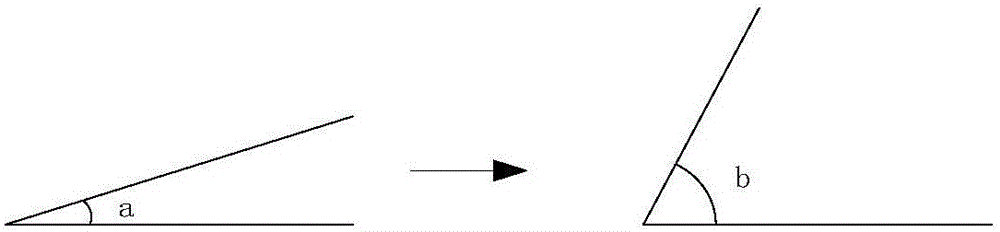
[0049] Wherein, when an external force acts on the first body 2 and / or the second body 3, the torsion force generated by the torsion force generating body 11 makes the torsion force generating body 11 bend, thereby making the first body 2 and the second body 3 The current angle between them is transformed from the first angle to a second angle different from the first angle. When the extern...

Embodiment 2

[0063] Based on the same inventive concept as the first embodiment of the present application, the second embodiment of the present application also provides an electronic device, including:

[0064] first subject;

[0065] second subject;

[0066] a rotating shaft device, the rotating shaft device including a torsion generating structure;

[0067] The torsion force generating structure includes a torsion force generating body, and a first connection structure and a second connection structure connected to opposite ends of the torsion force generating body;

[0068] Wherein, the first connection structure is fixedly arranged on the first body of the electronic device, and the second connection structure is fixedly arranged on the second body of the electronic device, when an external force acts on the When on the first body and / or the second body, the torsion force generated by the torsion force generating body causes the torsion force generating body to bend, thereby making...


PUM


Abstract

The invention discloses a rotating shaft device and an electronic device. The rotating shaft device comprises a torsion generating structure. The torsion generating structure comprises a torsion generating body, a first connecting structure and a second connecting structure, wherein the first connecting structure and the second connecting structure are arranged at the two opposite ends of the torsion generating body in a connected manner. The first connecting structure is fixedly arranged on a first body of the electronic device, and the second connecting structure is fixedly arranged on a second body of the electronic device. When external force acts on the first body and/or the second body, the torsion generating body is bent by the torsion generated by the torsion generating body, then a current included angle between the first body and the second body is changed from a first angle into a second angle different from the first angle, and when the external force stops from being applied, the current included angle between the first body and the second body can be kept as the second angle under the supporting effect of the torsion generating body.

Description

technical field [0001] The invention relates to a rotating shaft structure, in particular to a rotating shaft device and electronic equipment. Background technique [0002] With the continuous advancement of science and technology, the continuous popularization of electronic devices such as mobile phones and notebook computers, people's lifestyles have also undergone great changes. [0003] In the prior art, there are mainly two types of rotating shafts arranged between the main bodies of electronic equipment: one is a covered rotating shaft structure; the other is an end-face sliding friction rotating shaft structure. The friction between the parts reflects the torque and realizes the rotation. For example, a covered shaft structure can be set between the display screen and the host computer of a notebook computer. Then, under the action of an external force, the covered shaft structure generates torsion, and under the action of the torsion, it is realized by friction betw...

Claims


Application Information

Patent Timeline
Patent Type & Authority Applications(China)
IPC IPC(8): F16C11/04
Inventor 元春峰辛志峰
Owner LENOVO (BEIJING) LTD
Why Eureka
Try Eureka