Bearing rolling needle holder

A cage and needle roller technology, used in bearing components, shafts and bearings, mechanical equipment, etc., can solve the problems of long time, not in place, and difficulty in pressing needle rollers, and achieve the effect of convenient assembly and less time-consuming

Active Publication Date: 2015-12-09
NINGBO ZHONGHE AUTO PATS
View PDF9 Cites 2 Cited by
  • Summary
  • Abstract
  • Description
  • Claims
  • Application Information

AI Technical Summary

Problems solved by technology

[0002] The existing bearing needle roller cage is generally a one-piece metal structure. During assembly, the cage needs to be placed on the inner ring first, and then the needle rollers are pressed into the needle roller grooves on the cage. Pressing in one by one, the axis of the cage will g

Method used


Image

  • Bearing rolling needle holder
  • Bearing rolling needle holder
  • Bearing rolling needle holder

Examples


Embodiment Construction

[0014] The present invention will be further described in detail below in conjunction with the accompanying drawings and embodiments.

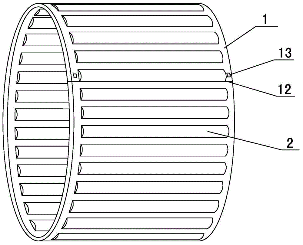
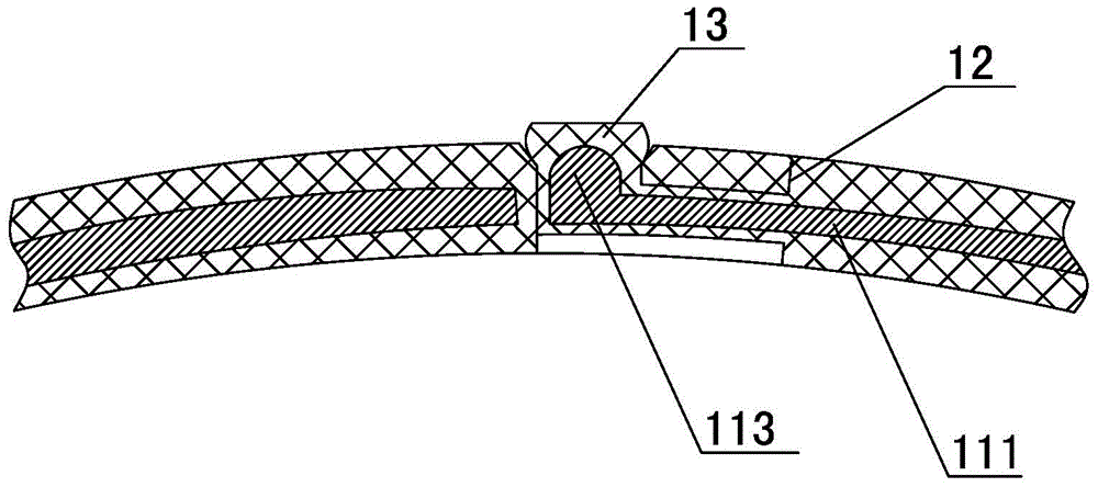
[0015] This preferred embodiment is figure 1 and 3 Shown is a bearing needle roller cage. The cage body 1 is composed of two connecting rings and a plurality of spacer strips arranged between the two connecting rings for isolating adjacent needle rollers 2. The cage body 1 is A disconnection part 12 is provided in the axial direction for opening the cage body 1, and one side of the disconnection part 12 is provided with a buckle 13 bayonet-connected with the other side. Wherein, the diameter of the head of the buckle 13 is larger than the diameter of the bayonet socket, and is pressed through during assembly.

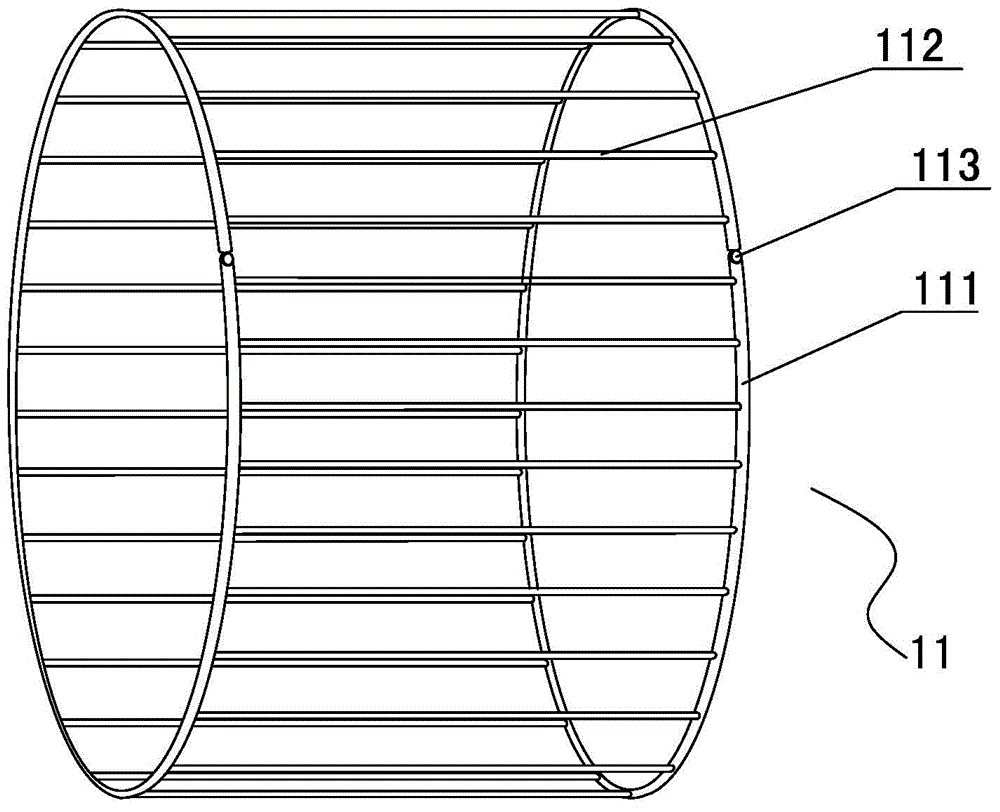
[0016] In this embodiment, the disconnection point 12 is arranged on the connecting ring, and may also be arranged on the connecting ring and the spacer bar at the same time. Cage body 1 consists of figure 2 The shown metal frame 1...


PUM


Abstract

The invention discloses a bearing rolling needle cage. A cage body consists of multiple separation strips for separating adjacent rolling needles and two connecting rings for respectively connecting the end parts of the two ends of each separation strip; a disconnecting place for opening the cage body is axially arranged on the cage body; one edge of the disconnecting place is provided with a buckle connected with a bayonet on the other edge; and the diameter of the head part of the buckle is larger than the diameter of the bayonet. The bearing rolling needle cage has the following advantages that as the disconnecting place is arranged on the cage body, after the rolling needles are quickly assembled, the cage body can coat an inner ring after being opened from the disconnecting place and the projection on one edge of the crack is connected with the other edge, so that the assembly is convenient and consumes little time; and preferably, the cage body consists of an openable metal framework and a shape layer wrapping the metal framework, and as the shape layer is preferably manufactured from PEEK which is better in deformation and recovery performance, the cage body can be opened conveniently and the recovered shape cannot be changed.

Description

technical field [0001] The invention relates to an automobile bearing, in particular to a bearing needle roller cage. Background technique [0002] The existing needle roller cage of the existing bearing is generally a one-piece metal structure. During assembly, the cage needs to be placed on the inner ring first, and then the needle rollers are pressed into the needle roller grooves on the cage. Pressing in one by one, the axis of the cage will gradually deviate from the axis of the inner ring, and the rest of the cage will be close to the inner ring, making it difficult or not in place for the last few needle rollers to be pressed in, and it needs to be adjusted many times before It took a long time to complete and needs to be improved urgently. Contents of the invention [0003] The technical problem to be solved by the present invention is to provide a bearing needle roller cage which is easy to install and takes a short time to install on the inner ring of the bearin...

Claims


Application Information

Patent Timeline
IPC IPC(8): F16C33/46
Inventor 鲍德夫
Owner NINGBO ZHONGHE AUTO PATS
Why Eureka
Try Eureka