Contrast anti-interference micro-motion step planar reflector laser interferometer and calibration method and measurement method
A technology of plane mirror and laser interferometer, which can be used in measurement devices, instruments, optical devices, etc., and can solve problems such as poor anti-environmental interference ability.
- Summary
- Abstract
- Description
- Claims
- Application Information
AI Technical Summary
Problems solved by technology
Method used
Image
Examples
Embodiment 1
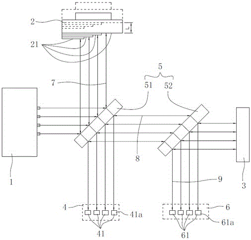
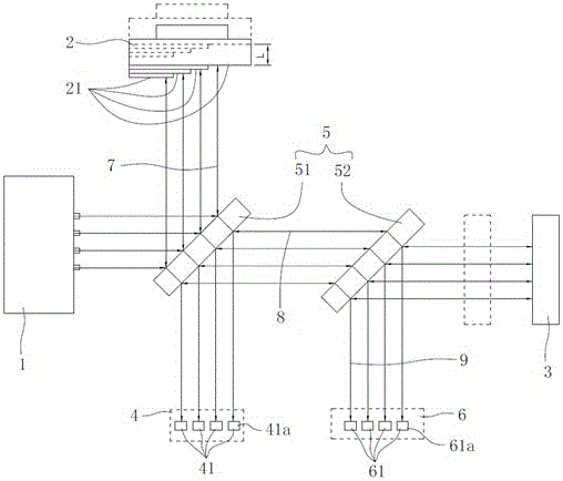
[0045] Embodiment 1, as shown in the figure, a comparative anti-interference laser interferometer with micro-movement stepped mirror, including a laser source 1, a micro-moved stepped mirror 2, an interferometric photodetector group 4, and a moving plane reflector Mirror 3, beam splitter group 5 and micro-motion platform 10, the micro-movement step plane reflector is arranged on the micro-motion platform 10, the laser source 1 emits a z beam of laser beams to the beam splitter group 5, wherein z is a positive integer greater than or equal to 2, the interferometric photodetector group 4 includes z interferometric photodetectors, each interferometric photodetector 41 corresponds to a laser beam, and the micro-movement steps The reflective surface of the plane mirror 2 includes z reflective planes 21, and the z reflective planes 21 are arranged in a stepped manner. Each reflective plane 21 corresponds to a laser beam, and each laser beam passes through the beam splitter group 5 A...
Embodiment 2
[0050] Embodiment 2: As shown in the figure, a calibration method for a contrastive anti-interference micro-moving step mirror laser interferometer includes the following steps:
[0051] Step 1. Position adjustment: adjust the laser source 1, the micro-movement stepped mirror 2, the beam splitter group 5, the interferometric photodetector group 4, the reflectance measurement photodetector group 6, the moving plane mirror 3 and the micro-motion platform 10 position;
[0052] Step 2. Adjusting the optical path: start the laser source 1, and further precisely adjust the fine-motion step plane reflector 2, the beam splitter group 5, the interferometric photodetector group 4, the reflection measurement photodetector group 6, and the moving plane reflector 3 and the position of the micro-movement platform 10, so that the optical path of the laser interferometer meets the design requirements;
[0053]Step 3, generate the strongest interference database: select an interferometric pho...
Embodiment 3
[0061] Implementation 3: As shown in the figure, a measurement method using a comparative anti-interference micro-moving step mirror laser interferometer and a calibration method:
[0062] In the actual measurement environment, it is assumed that the signal reading measured by the calibration reflectance measurement photodetector 61a is x, the signal reading obtained by the calibration interferometric photodetector 41a is y, and the x value and the y value are at the strongest Comparisons are made in the interference database, the weakest interference database, and the 1 / n wavelength interference database. When the x value and y value match a certain set of values in the strongest interference database, this position is considered to be the strongest constructive interference position , when the x value and y value match a set of values in the weakest interference database, this position is considered as the weakest destructive interference position, when the x value and y ...
PUM
 Abstract
Description
Claims
Application Information
 - R&D
- Intellectual Property
- Life Sciences
- Materials
- Tech Scout
- Unparalleled Data Quality
- Higher Quality Content
- 60% Fewer Hallucinations
Browse by: Latest US Patents, China's latest patents, Technical Efficacy Thesaurus, Application Domain, Technology Topic, Popular Technical Reports.
© 2025 PatSnap. All rights reserved.Legal|Privacy policy|Modern Slavery Act Transparency Statement|Sitemap|About US| Contact US: help@patsnap.com


