Magnetic micro-displacement platform type ladder angle mirror laser interferometer, calibration method and measurement method

A corner mirror, interferometric measurement technology, applied in measurement devices, instruments, optical devices, etc., can solve problems such as poor anti-environmental interference ability, and achieve the effect of improving accuracy and improving movement accuracy.

Active Publication Date: 2015-10-07
CHENGDU UNIV OF INFORMATION TECH
View PDF11 Cites 0 Cited by
  • Summary
  • Abstract
  • Description
  • Claims
  • Application Information

AI Technical Summary

Problems solved by technology

[0007] The purpose of the present invention is to provide a laser interferometer capable of resisting environmental interference in view of the shortcomings of current laser interferometers that are poor in anti-environmental interference

Method used


Image

  • Magnetic micro-displacement platform type ladder angle mirror laser interferometer, calibration method and measurement method
  • Magnetic micro-displacement platform type ladder angle mirror laser interferometer, calibration method and measurement method
  • Magnetic micro-displacement platform type ladder angle mirror laser interferometer, calibration method and measurement method

Examples


Embodiment 1

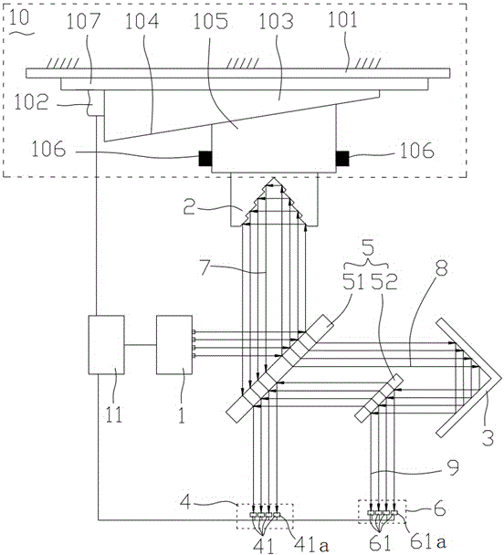
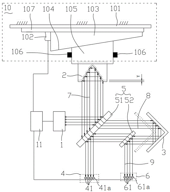
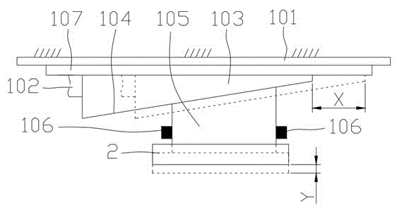
[0051]Embodiment 1, as shown in the figure, a magnetic micro-displacement platform-type step-angle reflector laser interferometer, including a laser source 1, a micro-moving step-angle reflector 2, an interferometric photodetector group 4, and a moving angle reflector 3. The beam splitter group 5 and the magnetic micro-displacement platform 10, the micro-movement stepped angle reflector 2 is arranged on the magnetic micro-displacement platform 10, and the laser source 1 emits a z-beam laser beam to the beam splitter group 5 , wherein z is a positive integer greater than or equal to 2, the interferometric photodetector group 4 includes z interferometric photodetectors, each interferometric photodetector 41 corresponds to a laser beam, and each laser beam After passing through the beam splitter group 5, it is divided into a first laser beam group 7 and a second laser beam group 8, and the first laser beam group 7 shoots to the micro-movement step angle reflector 2, and passes thr...

Embodiment 2

[0061] Embodiment 2, as shown in the figure, a calibration method for a magnetic micro-displacement platform-type step-angle mirror laser interferometer, including the following steps:

[0062] Step 1. Position adjustment: adjust the laser source 1, the micro-movement stepped angle mirror 2, the beam splitter group 5, the interferometric photodetector group 4, the reflection measurement photodetector group 6, the moving angle mirror 3 and the magnetic micro-displacement the location of platform 10;

[0063] Step 2, adjust the optical path: start the laser source 1, further finely adjust the micro-movement stepped angle reflector 2, the beam splitter group 5, the interferometric photodetector group 4, the reflection measurement photodetector group 6, and the moving angle reflector 3 and the position of the magnetic micro-displacement platform 10, so that the optical path of the laser interferometer meets the design requirements;

[0064] Step 3, generate the strongest interfer...

Embodiment 3

[0072] Embodiment 3, as shown in the figure, a measurement method using a magnetic micro-displacement platform-type step-angle mirror laser interferometer and a calibration method:

[0073] In the actual measurement environment, it is assumed that the signal reading measured by the calibration reflectance measurement photodetector 61a is x, the signal reading obtained by the calibration interferometric photodetector 41a is y, and the x value and the y value are at the strongest Comparisons are made in the interference database, the weakest interference database, and the 1 / n wavelength interference database. When the x value and y value match a certain set of values ​​in the strongest interference database, this position is considered to be the strongest constructive interference position , when the x value and y value match a set of values ​​in the weakest interference database, this position is considered as the weakest destructive interference position, when the x value and y...


PUM


Abstract

The invention relates to the field of precision measurement technologies and instruments, and in particular relates to a magnetic micro-displacement platform type ladder angle mirror laser interferometer, a calibration method and a measurement method. The magnetic micro-displacement platform type ladder angle mirror laser interferometer comprises a laser light source, a jog ladder angle mirror, an interferometry photodetector group, a moving angle mirror, a beam splitter group and a magnetic micro-displacement platform. The jog ladder angle mirror is arranged on the magnetic micro-displacement platform. The laser light source emits z laser beams to the beam splitter group. The magnetic micro-displacement platform type ladder angle mirror laser interferometer further comprises a reflection measurement photodetector group. A second laser beam group is reflected by the moving angle mirror to the beam splitter group to form a reflection laser beam group. Each laser beam of the reflection laser beam group goes to a reflection measurement photodetector. According to the invention, the laser interferometer determines the interference state of a laser interference beam according to the intensity of the reflection laser beam group, so as to realize interference prevention.

Description

technical field [0001] The invention relates to the field of precision testing technology and instruments, in particular to a magnetic micro-displacement platform-type stepped angle reflector laser interferometer, a calibration method and a measurement method. Background technique [0002] The emergence of lasers has enabled the rapid development of ancient interferometric technology. Lasers have the characteristics of high brightness, good directionality, monochromaticity and good coherence. Laser interferometry technology has been relatively mature. Laser interferometry system is widely used: measurement of precision length and angle, such as detection of linear scale, grating, gauge block, and precision screw; positioning detection system in precision instruments, such as control and correction of precision machinery; special purpose for large-scale integrated circuits Positioning detection systems in equipment and testing instruments; measurement of tiny dimensions, etc....

Claims


Application Information

Patent Timeline
Patent Type & Authority Applications(China)
IPC IPC(8): G01B9/02
Inventor 许诚昕张白凌味未马文英
Owner CHENGDU UNIV OF INFORMATION TECH
Why Eureka
Try Eureka