Self-sealing type ultraviolet lamp and manufacturing method thereof

An ultraviolet lamp and ultraviolet technology, which is applied in the field of ultraviolet lamps, can solve the problems of weakened cooling and heat dissipation efficiency of lamps, poor use efficiency of ultraviolet lamps, energy loss of ultraviolet lamps, etc., and achieves good cooling and heat dissipation effect, simple structure, and reduction of scrap. rate effect

Active Publication Date: 2015-12-09
广东君睿光电科技有限公司
View PDF6 Cites 2 Cited by
  • Summary
  • Abstract
  • Description
  • Claims
  • Application Information

AI Technical Summary

Problems solved by technology

When the current ultraviolet lamps are used in water treatment equipment, quartz sleeves must be used to cover the outside of the ultraviolet lamps to seal and waterproof the ultraviolet lamps. However, the use of quartz sleeves has the following defects: (1) The UV transmittance of the best quartz sleeve can only reach 80% to 90%, so it will cause the loss of energy of the ultraviolet lamp; (2) when the ultraviolet lamp is used in water treatment equipment, due to the Isolation makes the cooling effect of the water body on the lamp tube greatly weakened, so when the power density of the lamp tube is high, an expensive amalgam lamp must be used; (3) When 185nm ultraviolet rays need to be used to remove TOC or organic matter in water, the application The existing ultraviolet lamp tube must use a quartz sleeve, and the air sealed between the lamp tube and the quartz sleeve will produce a high concentration of O under the irradiation of 185nm ultraviolet rays. 3 , while O 3 It has a strong absorption effect on ultraviolet rays, coupled with the absorption of ultraviolet rays by the casing wall, the effective ultraviolet energy that can enter the water is greatly reduced, and the use efficiency of ultraviolet lamps is very poor.

Method used


Image

  • Self-sealing type ultraviolet lamp and manufacturing method thereof
  • Self-sealing type ultraviolet lamp and manufacturing method thereof
  • Self-sealing type ultraviolet lamp and manufacturing method thereof

Examples


Embodiment Construction

[0023] The present invention will be further elaborated below in conjunction with the accompanying drawings and embodiments.

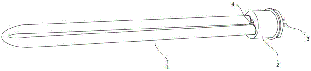
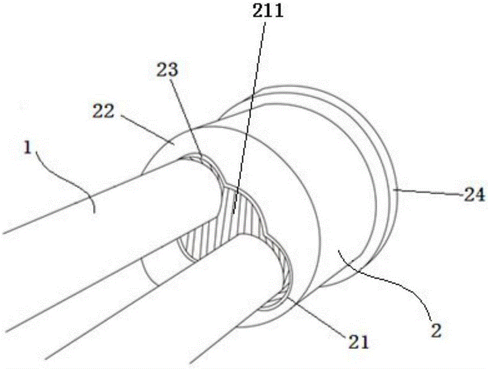
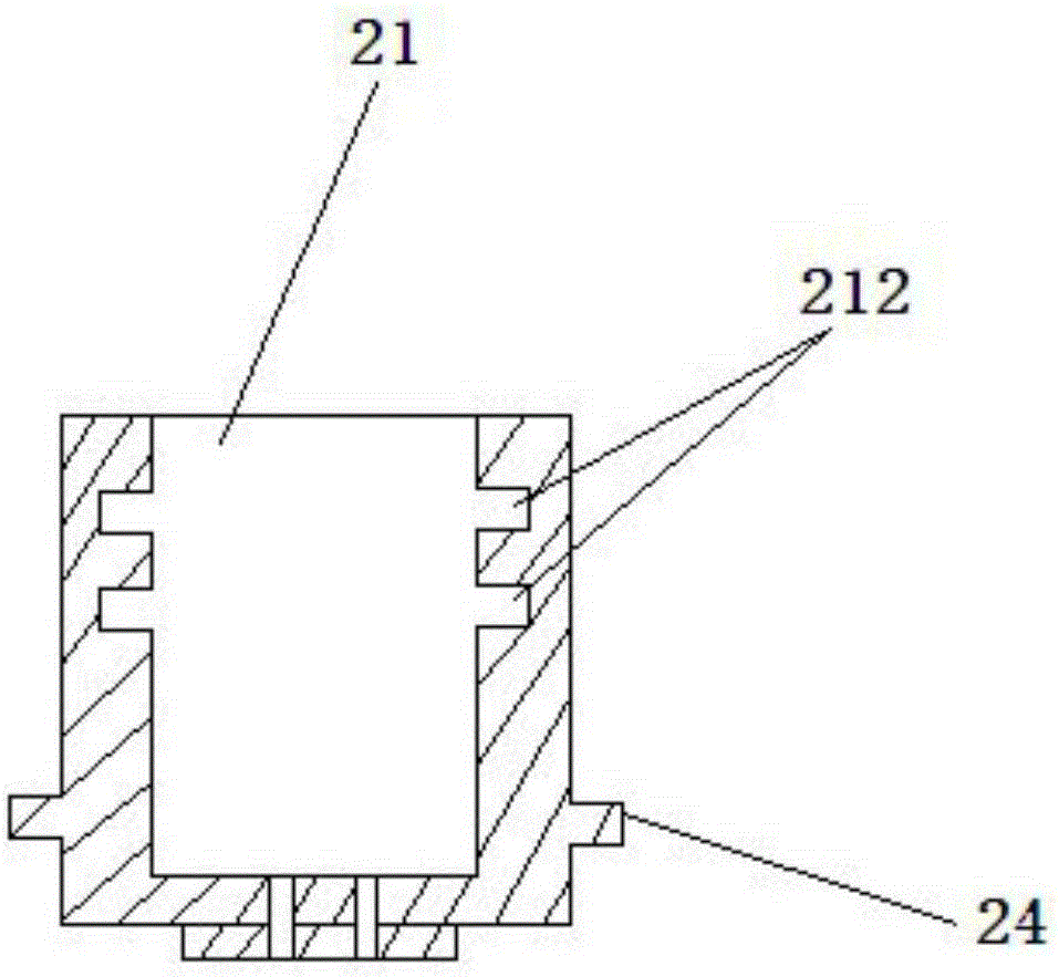
[0024] Such as figure 1 , figure 2 As shown, a self-sealing ultraviolet lamp includes an ultraviolet lamp tube 1 and a lamp holder 2. The ultraviolet lamp tube 1 is a U-shaped tube with metal electrodes 3 protruding from both ends of the same side. The lamp holder 2 is provided with a The positioning hole 21 into which the ultraviolet lamp 1 is inserted, the positioning hole 21 is provided with two holes and a glue filling hole 211, the glue filling hole is located between the two holes and communicates with the two holes. The two electrodes 3 on the side are respectively inserted into the corresponding holes and packaged with the lamp cap 2, and the ends of the electrodes 3 protrude from the bottom of the lamp cap 2 and are exposed outside the lamp cap 2. The apertures of the two holes are slightly larger than the diameter of the ultraviolet lamp tu...


PUM


Abstract

The invention discloses a self-sealing type ultraviolet lamp which comprises an ultraviolet lamp tube and a lamp holder. A positioning hole is arranged in the lamp holder, wherein the lamp tube is inserted into the positioning hole. The ultraviolet lamp tube is a U-shaped lamp tube. The ultraviolet lamp tube is provided with two electrodes on the same side. One end, which is provided with the electrodes, of the ultraviolet lamp tube is packaged in the lamp holder through the positioning hole, extends out of the lamp holder from the bottom of the lamp holder, and is exposed. The self-sealing type ultraviolet lamp is characterized in that a space between the wall of the inserted end of the ultraviolet lamp tube and the positioning hole is filled with an insulating sealant, and the ultraviolet lamp tube and the lamp holder are in seal connection through the insulating sealant. The lamp tube and the lamp holder are connected through the insulating sealant, so that waterproof and sealing performances are great. The wall of the lamp tube can directly contact water, and leakage is prevented. All ultraviolet energy emitted by the lamp tube can enter water without energy loss. The rubber elasticity of the insulating sealant can provide buffer protection for the lamp tube, which reduces scrap rate in a special design process of the ultraviolet lamp tube.

Description

technical field [0001] The invention relates to an ultraviolet lamp applied to water treatment equipment, in particular to a self-sealing ultraviolet lamp and a manufacturing method thereof. Background technique [0002] Low-pressure ultraviolet lamps in the UVC band are often used in water treatment equipment to play a role in sterilization or photolysis purification. When the current ultraviolet lamps are used in water treatment equipment, quartz sleeves must be used to cover the outside of the ultraviolet lamps to seal and waterproof the ultraviolet lamps. However, the use of quartz sleeves has the following defects: (1) The UV transmittance of the best quartz sleeve can only reach 80% to 90%, so it will cause the loss of energy of the ultraviolet lamp; (2) when the ultraviolet lamp is used in water treatment equipment, due to the Isolation makes the cooling effect of the water body on the lamp tube greatly weakened, so when the power density of the lamp tube is high, an...

Claims


Application Information

Patent Timeline
Patent Type & Authority Applications(China)
IPC IPC(8): H01J61/36
Inventor 林若沙
Owner 广东君睿光电科技有限公司
Why Eureka
Try Eureka