Reconfigurable mono-pulse antenna

A monopulse and antenna technology, applied in the direction of antenna, antenna array, radiation element structure, etc., can solve the complex problems of monopulse antenna, and achieve the effect of small size, good circular polarization characteristics, and low profile

Active Publication Date: 2015-12-09
SOUTHEAST UNIV
View PDF6 Cites 7 Cited by
  • Summary
  • Abstract
  • Description
  • Claims
  • Application Information

AI Technical Summary

Problems solved by technology

However, monopulse antennas based on microstrip always require

Method used


Image

  • Reconfigurable mono-pulse antenna
  • Reconfigurable mono-pulse antenna
  • Reconfigurable mono-pulse antenna

Examples


Embodiment Construction

[0032] The present invention will be further described below in conjunction with the accompanying drawings.

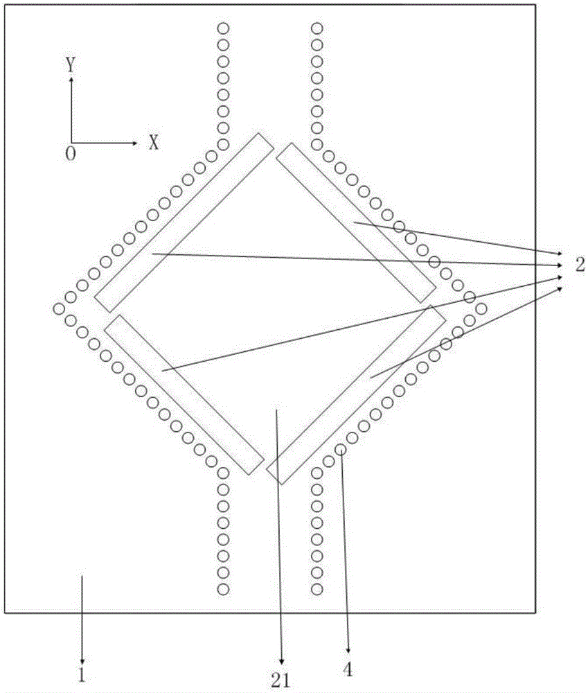
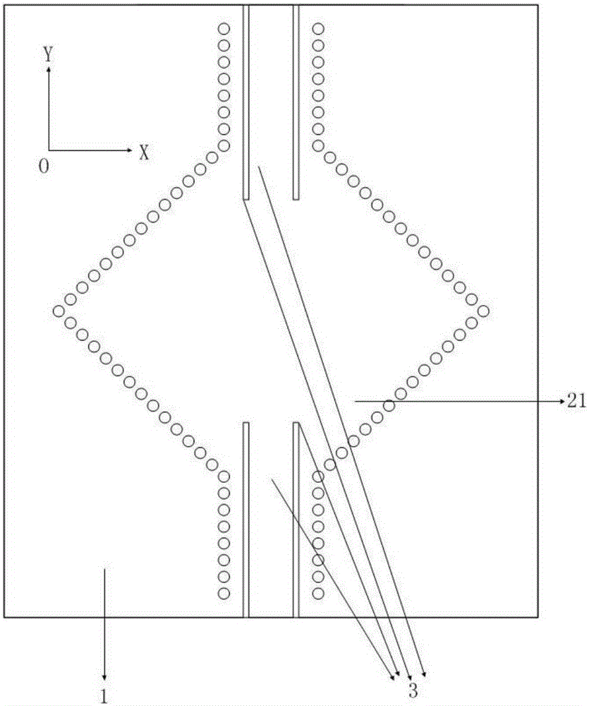
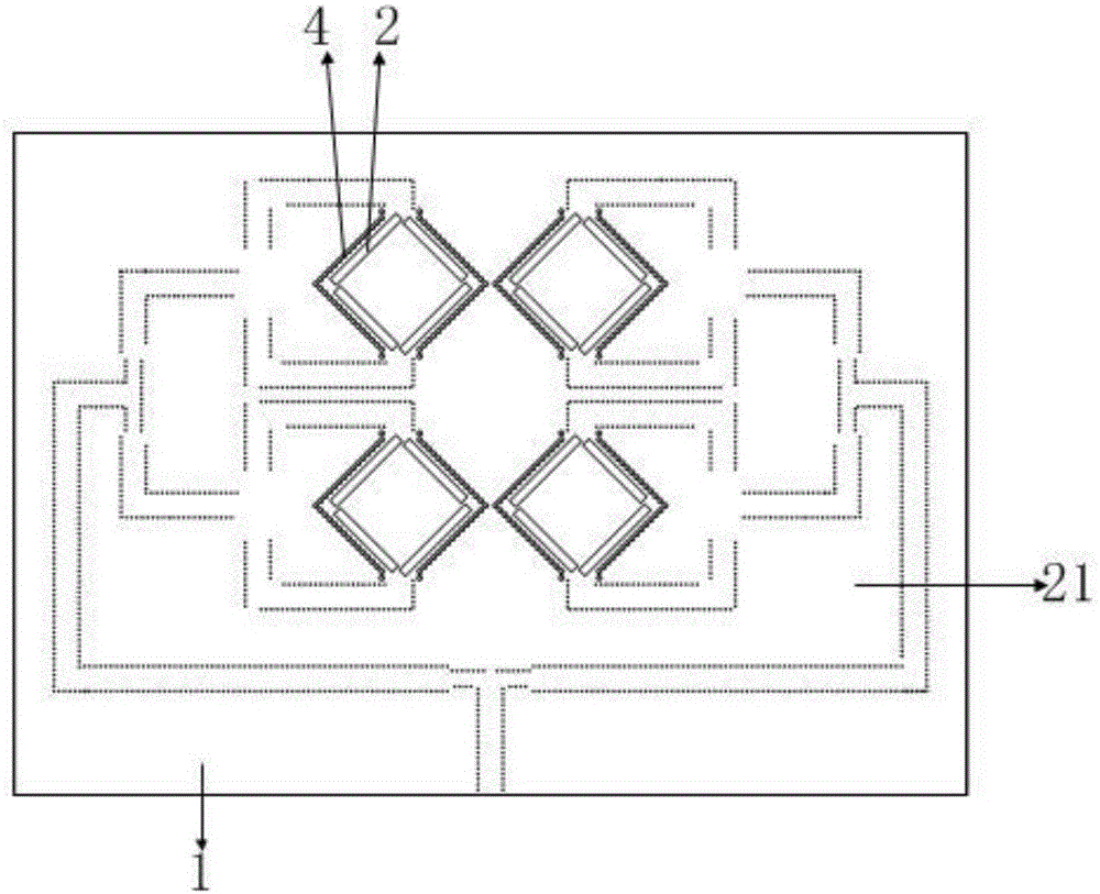
[0033] Such as figure 1 , 2 Shown is the antenna unit (or sub-array) of a small monopulse antenna, the working mode of the antenna unit (or sub-array) is the high-order degenerate mode of the square resonator 4; the antenna unit (or sub-array) includes The dielectric substrate 1 , the upper metal layer 21 , the lower metal layer 22 and metal through holes, the metal through holes penetrate the dielectric substrate 1 and connect the upper metal layer 21 and the lower metal layer 22 at the upper and lower ends respectively. The antenna has two input ports on a diagonal, and the two input ports are 180 degrees out of phase.

[0034] Specifically, four slots are etched on the upper metal layer 21 and around the resonant cavity 4 as radiation slots 2, and the radiation slots 2 serve as radiation structures of the antenna unit (or sub-array). A slit is etched on the lower...


PUM


Abstract

The invention provides a reconfigurable mono-pulse antenna. The reconfigurable mono-pulse antenna comprises fourantenna units arranged along longitudinal and transversal directions in a two-dimensional array manner, four switches in one-to-one correspondence with the antenna units, and a one-to-four equal-amplitude and equal-phase-position power distributor; each antenna unit comprises two feed ports; the feed ports at the two ends of each antenna unit are connected with the switches respectively through finite ground coplanar waveguide transmission lines; among the ports at the two ends of the antenna units, only one port is in the working state though the switch control; and four branches of the one-to-four equal-amplitude and equal-phase-position power distributor are connected with the switches respectively, and can feed one port of the two ports of the four antenna units separately through the switch control. The input ports of the antenna units can be changed by changing the states of the switches so as to change the phase positions of the antenna units to form three different antenna patterns: sum beams, azimuth difference beams and pitch difference beams so as to realize mono-pulse positioning.

Description

technical field [0001] The invention belongs to antenna technology, in particular to a reconfigurable monopulse antenna. Background technique [0002] In order to accurately obtain the angle and velocity of the target, monopulse radar plays an important role. As the most important part of monopulse radar, monopulse antenna is always the focus of people's research. The implementation principle of the monopulse antenna is relatively simple, that is, by changing the phases of the radiation elements in different quadrants, the sum beam, azimuth difference beam and elevation difference beam can be realized. Early monopulse antennas were mainly realized by Cassegrain antennas, and multimode horns or other multimode technologies were used to obtain the sum and difference signals of monopulse antennas, but they had the disadvantages of large size and unfavorable antenna movement. In the subsequent development, due to the small size, light weight, and low cost of the microstrip ant...

Claims


Application Information

Patent Timeline
IPC IPC(8): H01Q25/02H01Q21/00H01Q1/38
Inventor 郝张成王宏慧
Owner SOUTHEAST UNIV
Why Eureka
Try Eureka