A Compact Circularly Polarized Microstrip Antenna and Its Antenna Array

A technology of microstrip antenna and circular polarization, which is applied to the combination of antenna units with different polarization directions, the structural form of antennas, and radiation elements, etc., which can solve the problems of unfavorable antenna array miniaturization and large array element spacing, and achieve compact structure , reduce the size of the antenna, extend the effect of the current path

Active Publication Date: 2017-08-18
GUILIN UNIV OF ELECTRONIC TECH
View PDF7 Cites 0 Cited by
  • Summary
  • Abstract
  • Description
  • Claims
  • Application Information

AI Technical Summary

Problems solved by technology

Due to the coupling between the antenna elements, in order to reduce the influence of the coupling on the performance of each antenna element, at present, the element spacing of the general microstrip antenna array is 0.5λ (λ is the wavelength of the electromagnetic wave in the medium), the microstrip Due to circular polarization interference, the circularly polarized antenna array has relatively large element spacing, at least 0.83λ, which is not conducive to the miniaturization of the antenna array

Method used


Image

  • A Compact Circularly Polarized Microstrip Antenna and Its Antenna Array
  • A Compact Circularly Polarized Microstrip Antenna and Its Antenna Array
  • A Compact Circularly Polarized Microstrip Antenna and Its Antenna Array

Examples


Embodiment 1

[0025] Embodiment 1 of the antenna array formed by the compact circularly polarized microstrip antenna is as Figure 4 As shown, the above-mentioned three embodiments of compact circularly polarized microstrip antennas constitute linear antenna arrays, and three identical power dividers are connected to the feeders of the three array elements one by one to input signals of equal amplitude and phase, and three The array elements are arranged in a straight line on the same plane, and the line connecting the centers of the three array elements is a straight line.

[0026] In this example, the operating frequency of the microstrip circularly polarized antenna array is 2.4GHz, and the wavelength λ in the substrate medium is 59.55mm. The distance D between the elements of the microstrip circularly polarized antenna array (that is, the distance between adjacent radiation patches) is 35mm, D=0.6λ.

[0027] In this example, the return loss bandwidth of the microstrip circularly polari...

Embodiment 2

[0029] Embodiment 2 of the antenna array composed of the compact circularly polarized microstrip antenna Figure 5 As shown, 2×2 above-mentioned compact circularly polarized microstrip antennas are implemented as array elements to form a square array antenna array, and 4 identical power dividers are connected to the feeders of 4 array elements one by one to input signals of equal amplitude and phase , 4 array elements are arranged in a 2×2 square array on the same plane.

[0030] In this example, the operating frequency of the microstrip circularly polarized antenna array is 2.4 GHz, the wavelength λ in the substrate medium is 59.55 mm, and the distance D between array elements is 35 mm, D=0.6λ.


PUM


Abstract

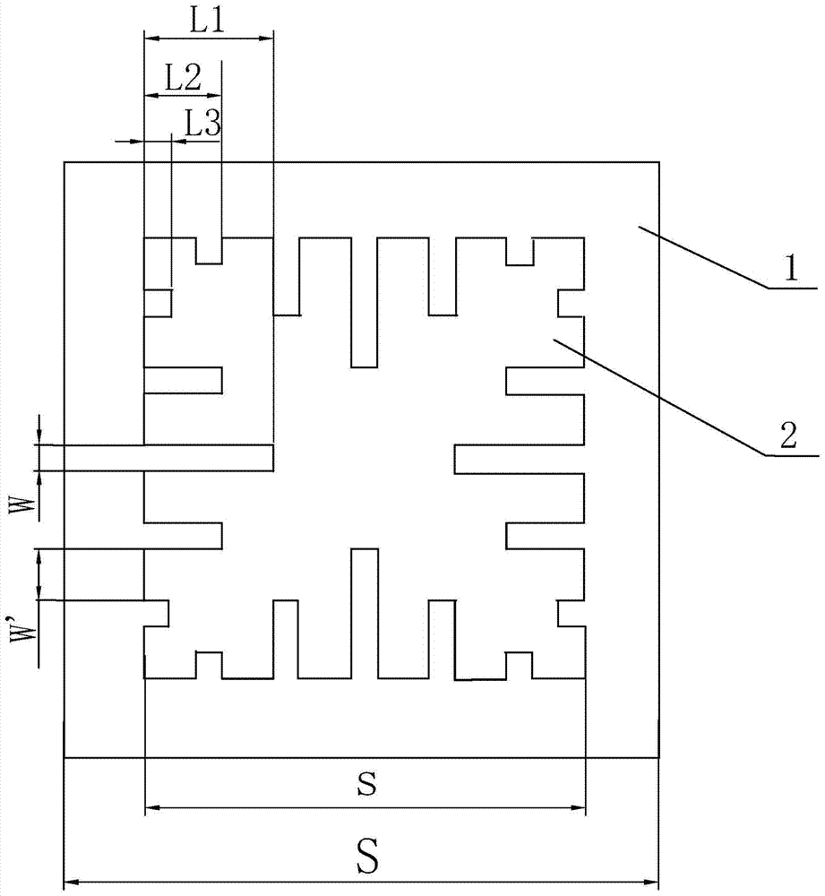
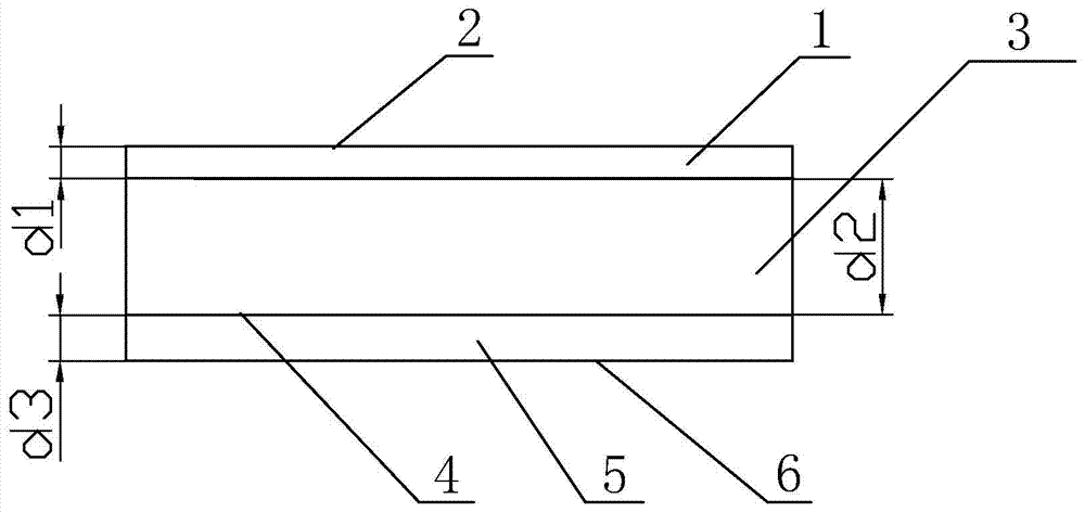
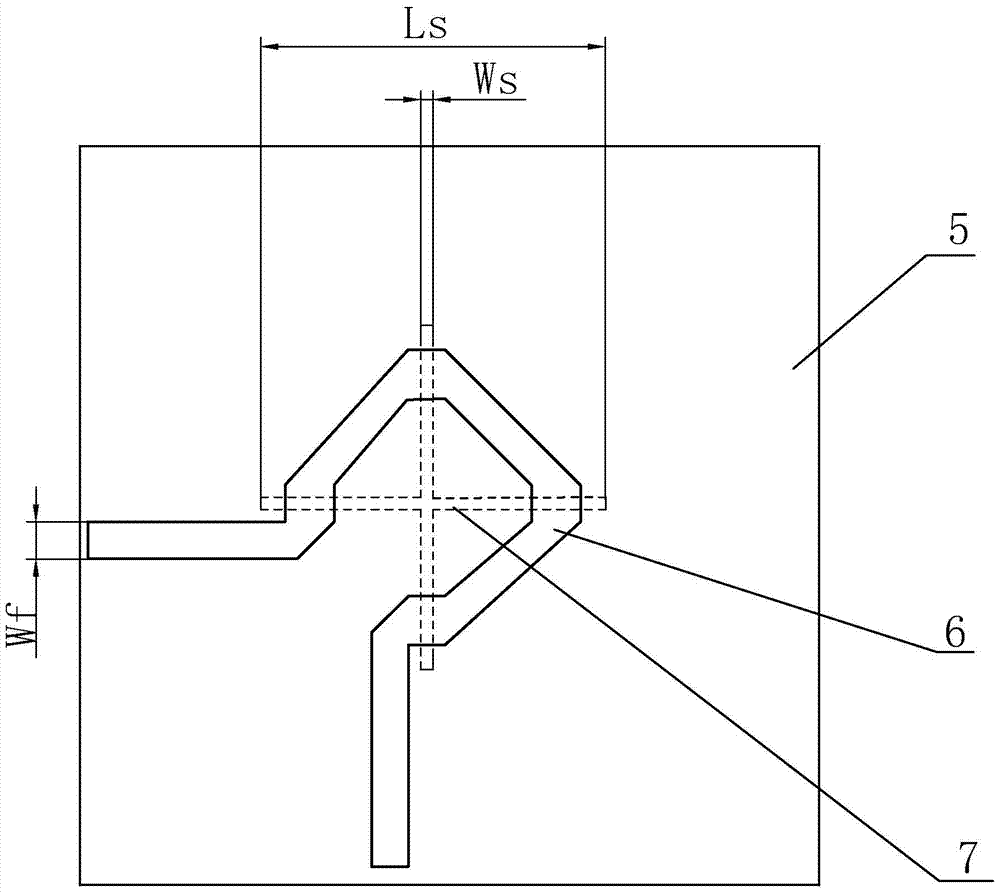
The invention relates to a compact circularly polarized microstrip antenna and its antenna array. The upper and lower dielectric plates and the substrate of the circularly polarized microstrip antenna are the same square, the square radiation patch is attached to the surface of the upper dielectric plate, and the substrate is attached to the upper surface of the upper dielectric plate. Attached to the upper surface of the lower dielectric board, the microstrip feeder is attached to the lower surface of the lower dielectric board. There is an air layer between the substrate and the upper dielectric board. In the center of the substrate, there are cross grooves in which vertical and horizontal grooves bisect each other vertically and horizontally. There are 3 to 7 grooves on each side of the radiation patch on the top layer. The groove on the center line is the deepest, and the depth of the grooves on both sides gradually decreases. The groove of is symmetrical about the center of the radiation patch. The compact circularly polarized microstrip antenna is an antenna array composed of array elements. Each power divider is connected to each array element feeder, and multiple array elements are arranged in a straight line on the same plane, or arranged in a square array on the same plane. The invention has better circular polarization characteristics, reduces the size of the antenna, reduces the distance between elements of the antenna array to 0.6λ, and has a compact structure of the antenna array.

Description

technical field [0001] The invention relates to the technical field of receiving antennas in communication, in particular to a compact circularly polarized microstrip antenna and an antenna array thereof. Background technique [0002] The circularly polarized microstrip antenna is a patch-shaped antenna composed of a metal copper sheet attached to a medium. The circularly polarized microstrip antenna includes a radiation patch on the top layer, an air layer and a bottom feeder. Circularly polarized microstrip antennas are mainly used for receiving antennas and require better circular polarization characteristics. At present, the circularly polarized microstrip antenna radiation patch has symmetrical grooves of the same depth on the four sides to extend the surface current path of the radiation patch and reduce the size of the antenna. While making the antenna array compact, it also ensures the circular pole of the antenna. characteristics. However, the existence of uniform...

Claims


Application Information

Patent Timeline
Patent Type & Authority Patents(China)
IPC IPC(8): H01Q13/08H01Q1/38H01Q21/24
Inventor 高喜李中明王静
Owner GUILIN UNIV OF ELECTRONIC TECH
Why Eureka
Try Eureka