Dual-circularly-polarized broadband wide-beam antenna

A dual circular polarization, wide bandwidth technology, applied in the direction of the antenna, antenna parts, antenna grounding switch structure connection, etc., can solve the problems of large lateral size, difficult to good axial ratio characteristics, etc., to achieve wide axial ratio beam, good circular Polarization characteristics, the effect of increasing the horizontal plane gain

Active Publication Date: 2021-07-30
XIDIAN UNIV +1
View PDF13 Cites 1 Cited by
  • Summary
  • Abstract
  • Description
  • Claims
  • Application Information

AI Technical Summary

Problems solved by technology

The microstrip antenna can radiate by changing the ground structure and adding vertical current near the main radiator. It can realize a wide half-power beam in a narrow operating frequency band, but it is difficult to maintain a good axial ratio characteristic in the beam.
In the prior art, multiple annular choke grooves are added to the horn mouth surface to broaden the half-power beam, but its lateral dimension is too large

Method used


Image

  • Dual-circularly-polarized broadband wide-beam antenna
  • Dual-circularly-polarized broadband wide-beam antenna
  • Dual-circularly-polarized broadband wide-beam antenna

Examples


Embodiment 1

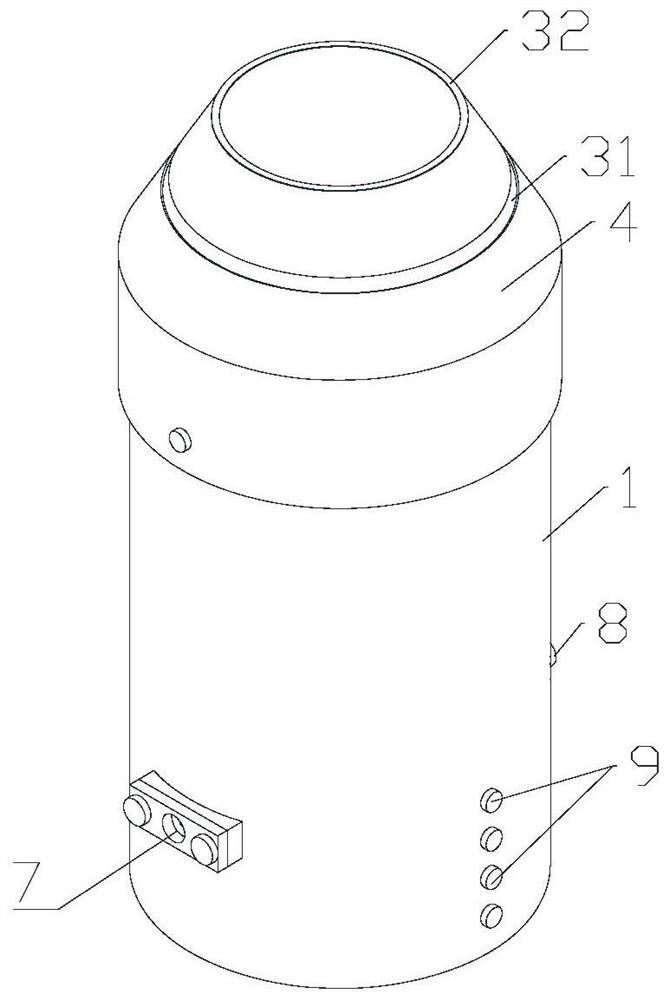
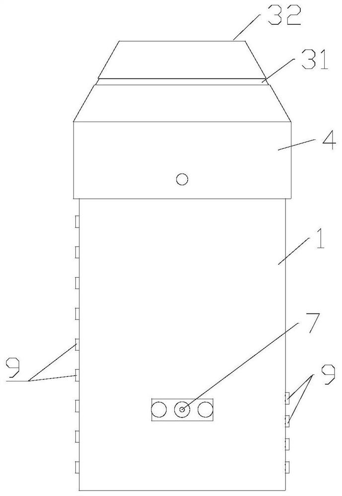
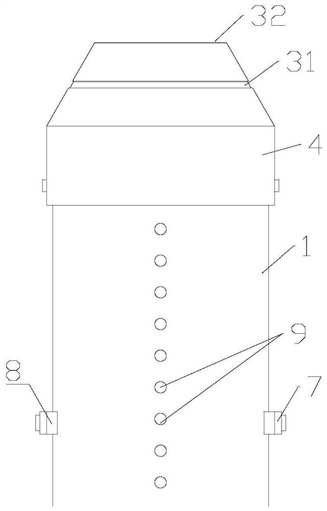
[0035] see Figure 1 to Figure 6 , a dual circularly polarized wide-bandwidth beam antenna, comprising a circular waveguide 1, a feed probe 5, a load probe 6, a bulkhead phase shifter 2 and a metal ring group; the feed probe 5, the load Both the probe 6 and the diaphragm phase shifter 2 are located in the circular waveguide 1, and the feeding probe 5 and the load probe 6 are separated on both sides of the diaphragm phase shifter 2; One end face of the circular waveguide 1 is closed, and the other end face is provided with an opening; the energy fed by the feeding probe 5 is converted by the diaphragm phase shifter to form a circularly polarized wave and then radiated outward from the opening; The metal ring group is located next to the opening for introducing a horizontal annular magnetic flow; the side wall of the circular waveguide 1 close to the opening is provided with a group of hollow grooves for introducing a vertical magnetic flow.

[0036]Through the circular wavegui...

Embodiment 2

[0038] On the basis of the above structure, at least two first vertical grooves 11 and at least two second vertical grooves 12 are arranged in the hollow groove group; the length of the first vertical groove 11 is longer than that of the second vertical groove 12 length, and the length directions of both are parallel to the axis of the circular waveguide 1; the first vertical slots 11 and the second vertical slots 12 are alternately arranged. The arrangement direction is clockwise or counterclockwise around the axis of the circular waveguide 1 . By adopting different slot depths to increase the pattern bandwidth of the antenna, it is more conducive to widening the bandwidth.

Embodiment 3

[0040] On the basis of the above structure, the opening is a circular mouth whose diameter is equal to the diameter of the circular waveguide 1; one end of the first vertical groove 11 extends to the edge of the opening, and the second vertical groove One end of 12 also extends to the edge of the opening, so that part of the electromagnetic wave is leaked and the axial ratio of the beam is improved.


PUM


Abstract

The invention provides a dual-circularly-polarized broadband wide-beam antenna. The antenna comprises a circular waveguide, a feed probe, a load probe, a partition plate phase shifter and a metal ring group; the feed probe, the load probe and the partition plate phase shifter are all located in the circular waveguide, and the feed probe and the load probe are located on the two sides of the partition plate phase shifter respectively. One end face of the circular waveguide is closed, and the other end face is provided with an opening; energy fed in by the feed probe is converted into circularly polarized waves through the partition plate phase shifter and then is radiated outwards from the opening; the metal ring group is positioned beside the opening and is used for introducing horizontal annular magnetic current; the side wall, close to the opening, of the circular waveguide is provided with a hollowed-out groove set used for introducing vertical magnetic current. Circularly polarized waves with directional radiation are formed through the circular waveguide and the partition plate phase shifter; horizontal annular magnetic current is introduced, and the half-power beam width is increased; the vertical magnetic current is introduced, the half-power beam width in the broadband is further improved, the difference value of the E theta sum in a certain beam is reduced, and the axial ratio beam width is improved.

Description

technical field [0001] The invention relates to the technical field of circularly polarized antennas, in particular to a dual circularly polarized wide bandwidth beam antenna. Background technique [0002] With the development of modern technology, people's information exchange is becoming more and more frequent. In recent years, in order to better transmit electromagnetic waves, satellite communications usually choose to use wide-beam circularly polarized antennas. In some special use environments, it is necessary to design an antenna with a wider beam in the communication system to transmit and receive electromagnetic waves, so as to realize communication between devices in a wide area. The designed antenna with a wider beam requires less radiation power drop within a certain beam range, and can effectively receive radio signals at low elevation angles, thereby achieving effective reception and transmission of electromagnetic waves in a larger range. [0003] In the prio...

Claims


Application Information

Patent Timeline
Patent Type & Authority Applications(China)
IPC IPC(8): H01Q1/36H01Q1/50H01Q3/34H01Q1/00H01Q15/24
CPCH01Q1/36H01Q1/50H01Q1/002H01Q3/34H01Q15/242
Inventor 刘能武夏良新傅光云宇祝雷
Owner XIDIAN UNIV
Why Eureka
Try Eureka