
Active filtering method and filter

A technology of power filters and controllers, applied in AC networks to reduce harmonics/ripples, harmonic reduction devices, etc., can solve the problem of high controller requirements, affecting APF harmonic compensation accuracy, reducing system stability, etc. problem, achieve high compensation accuracy and dynamic response speed, reduce the difficulty of software design, and reduce the effect of hardware design difficulty

Inactive Publication Date: 2015-12-09
深圳市海思瑞科电气技术有限公司
View PDF5 Cites 1 Cited by
  • Summary
  • Abstract
  • Description
  • Claims
  • Application Information

AI Technical Summary

Problems solved by technology

[0004] Harmonic current detection part: (1) If the FFT method is used, all harmonics can be detected, but the response time of one cycle is required, which greatly reduces the dynamic response speed of the system and requires the controller higher
(2) The harmonic current detection technology based on the instantaneous reactive power theory can directly obtain all harmonic currents, and the response speed is very fast, but in this way, all harmonics can only be controlled together, and the bandwidth limitation will affect APF harmonic compensation precision
(3) If the specified sub-harmonic current detection technology based on the instantaneous reactive power theory is used, two coordinate transformations are required to detect each harmonic current. When the selected harmonics are large, the requirements for the controller Very high, or use multi-CPU cooperative control, which will increase the cost and reduce the stability of the system
According to the current mainstream control chips in the market, on the basis of considering the cost, if the number of harmonics to be filtered is too large, it is difficult to meet the requirements. Therefore, in practical applications, the harmonics that can be selected when filtering the specified harmonics are often selected. The number of times generally does not exceed 6

Method used


Image

  • Active filtering method and filter
  • Active filtering method and filter
  • Active filtering method and filter

Examples


Embodiment Construction

[0038] The technical solution of the present invention will be described in detail below in conjunction with the accompanying drawings and specific embodiments, so as to understand the essence of the present invention more clearly and intuitively.

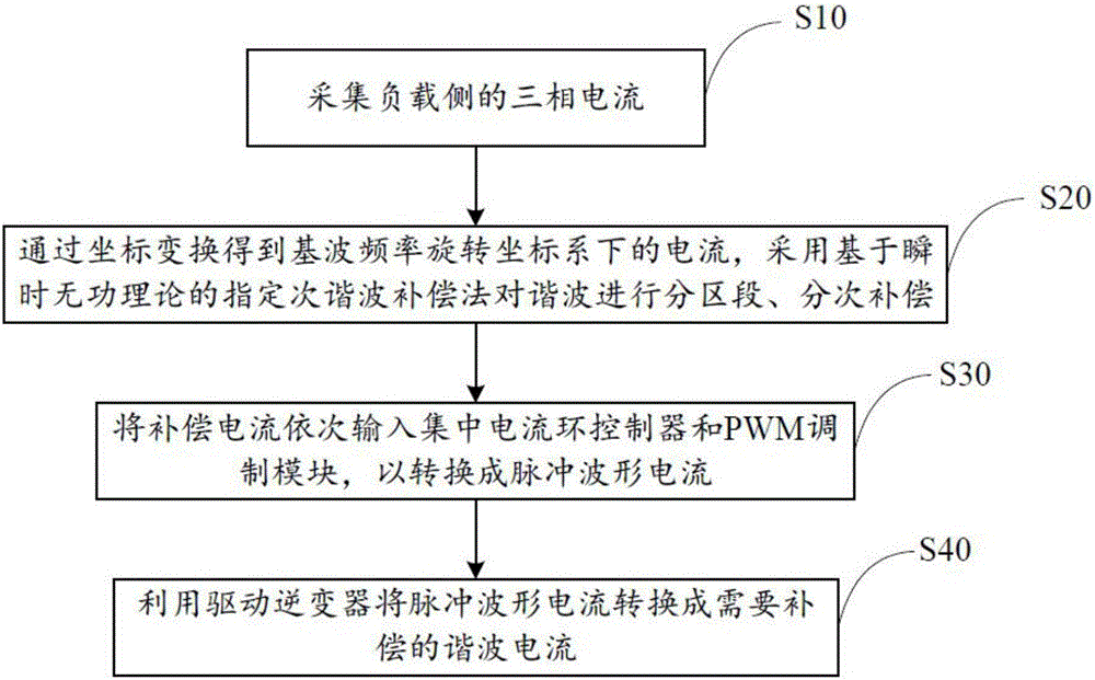
[0039] refer to figure 1 As shown, the active filtering method of the present invention can be used in power systems or other power quality products, mainly for filtering multiple harmonics and performing active compensation. The method mainly includes the following steps:

[0040] S10: collect the three-phase current on the load side;

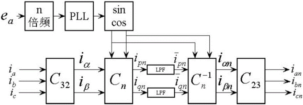
[0041] S20: Obtain the current in the rotating coordinate system at the fundamental frequency through coordinate transformation, and use the specified sub-harmonic compensation method based on the instantaneous reactive power theory to compensate the harmonics in sections and stages;

[0042] S30: Input the compensation current into the centralized current loop controller and the PWM modulation m...


PUM


Abstract

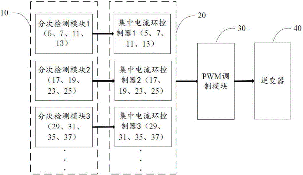
The present invention relates to an active filtering method and a filter. The filter comprises a gradation detection module, a concentration electric current loop controller, a PWM module and an inverter. The filtering method comprises the following steps: employing the gradation detection module to collect a three-phase current of a load side; obtaining a current under a fundamental frequency rotating coordinate system through transformation of coordinates; employing a selective harmonic compensation method based on an instantaneous reactive power theory to perform compensation in sections and times; in order inputting the compensating current into the concentration electric current loop controller and the PWM module to convert the compensating current to an impulse waveform current; and converting the impulse waveform current to a harmonic current required to be compensated through driving the inverter. According to the invention, the problems of the slow system dynamic response speed of the FFT (Fast Fourier Transformation) mode, the bandwidth problem existing in the harmonic detection technology based on the instantaneous reactive power theory, and the compensation precision problem existing in the selective harmonic current detection technology are solved; and moreover, the cost of the device is reduced, and the stability of the system is improved.

Description

technical field [0001] The invention relates to the technical field of electronic filters, in particular to an active power filtering method and a filter. Background technique [0002] At present, from the perspective of harmonic current detection, active power filters are mainly divided into: harmonic current detection based on FFT (Fast Fourier Transformation, Fast Fourier Transformation), harmonic current detection based on instantaneous reactive power theory, and non-harmonic current detection. APF (Activepowerfilter, active power filter). On this basis, for specific occasions, some scholars have proposed an algorithm for eliminating specified sub-harmonics, extending the theory of instantaneous reactive power to sub-detection of each sub-harmonic, and then superimposing to obtain the total harmonic current. The harmonic current passes through the current controller to finally obtain the command modulation current signal, and then enters the PWM to obtain the correspond...

Claims


Application Information

Patent Timeline
IPC IPC(8): H02J3/01
CPCY02E40/40
Inventor 钟顺时李志超洪波
Owner 深圳市海思瑞科电气技术有限公司
Learn More