Draught fan drying system of dish-washing machine

A drying system and dishwasher technology, applied in the direction of tableware washing machine/rinsing machine, tableware washing machine/rinsing and rinsing machine parts, household cleaning devices, etc., can solve the problem of good drying effect, slow drying efficiency, and objects Corrosion and other problems, to achieve the effect of ensuring the drying effect, improving drying efficiency, and preventing adverse effects

Active Publication Date: 2015-12-16
WUHU MIDEA SMART KITCHEN APPLIANCE MFG CO LTD
View PDF5 Cites 20 Cited by
  • Summary
  • Abstract
  • Description
  • Claims
  • Application Information

AI Technical Summary

Problems solved by technology

[0004] 1) The first type is to use the fan to directly discharge the hot and humid air in the inner tank to the outside of the dishwasher. Although this method can quickly discharge the hot and humid air inside the inner tank and on the tableware, it will discharge the hot and humid air outside the dishwasher. The hot and humid air will be directly discharged to the cabinets and other furniture in the kitchen, which will condense on these objects to form water droplets. Long-term operation will have a bad impact on these objects, such as easy to cause these objects to rot (such as wooden cabinets decay) or affect the performance of these objects, etc.
[0005] 2) The second type is to install an internal circulating air duct condensation system in the dishwasher to gradually condense the hot and humid air in the inner tank. Although this method will not affect the external environment of the dishwasher, it often A bulky condenser is needed to realize this. This kind of drying system is expensive, and the drying efficiency is slow, and the drying effect is not as good as that of the first type of fan drying system mentioned above. It is difficult to meet the user's requirements for low-cost and high-performance products.

Method used


Image

  • Draught fan drying system of dish-washing machine
  • Draught fan drying system of dish-washing machine
  • Draught fan drying system of dish-washing machine

Examples


Embodiment Construction

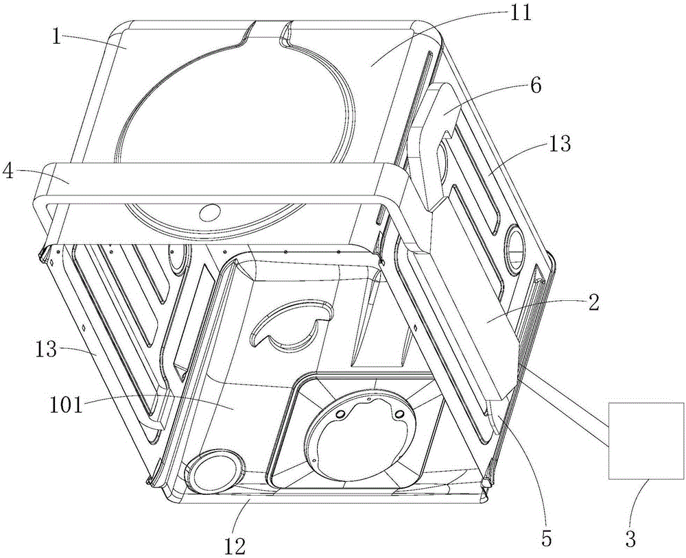
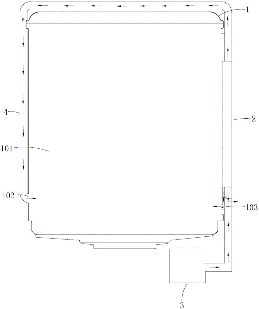
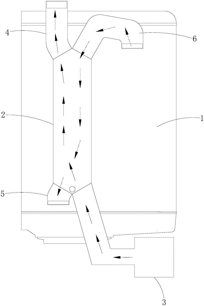
[0025] In order to make the object, technical solution and advantages of the present invention clearer, the present invention will be further described in detail below in conjunction with the accompanying drawings and embodiments. It should be understood that the specific embodiments described here are only used to explain the present invention, not to limit the present invention.

[0026] It should be noted that when an element is referred to as being “fixed” or “disposed on” another element, it may be directly on the other element or there may be an intervening element at the same time. When an element is referred to as being "connected to" another element, it can be directly connected to the other element or intervening elements may also be present.

[0027] It should also be noted that the orientation terms such as left, right, up, down, top, and bottom in the following examples are only relative concepts or refer to the normal use status of the product, and should not be ...


PUM


Abstract

The invention is suitable for the field of dish-washing machines, and discloses a draught fan drying system of a dish-washing machine. The draught fan drying system comprises an inner container with an inner cavity, a heat exchanger installed outside the inner container and a first draught fan installed outside the inner container. The heat exchanger is provided with at least one cold air flow passage and at least two hot air flow passages. The cold air flow passages and the hot air flow passages are alternately arranged in the heat exchanger at intervals. Inlets of the cold air flow passages are communicated with an air outlet of the first draught fan, outlets of the cold air flow passages and inlets of the hot air flow passages are communicated with the inner cavity, an outlet of at least one hot air flow passage is communicated with the inner cavity, and an outlet of at least one hot air flow passage is communicated with external air. According to the draught fan drying system, air obtained after heat exchanging is carried out through the hot air flow passages is divided into two parts to be exhausted out of the heat exchanger, one part of the air is directly exhausted out of the dish-washing machine, and the other part of the air flows back to the inner cavity again; in this way, bad influences on objects around the dish-washing machine can be avoided, cost is low, and the drying effect and the drying efficiency are also high.

Description

technical field [0001] The invention belongs to the field of dishwashers, in particular to a fan drying system for dishwashers. Background technique [0002] After the washing process of the dishwasher is finished (the rinsing stage is finished), the interior of the inner tank is a high-temperature and high-humidity environment. In this case, it is very unfavorable for the rapid drying of tableware. Dishwashers in the traditional technology dry tableware mainly through the residual heat left in the inner tank. Since this method does not need to add other parts, the structure of the drying system is simple and easy to implement; however, because the inner tank The hot and humid air has not been effectively discharged, so during the drying process, the hot and humid air in the inner tank will re-condense on the inner tank wall, inner door and tableware of the dishwasher, and its drying effect and drying efficiency are very poor, thereby reducing user satisfaction with the pro...

Claims


Application Information

Patent Timeline
Patent Type & Authority Applications(China)
IPC IPC(8): A47L15/48
CPCA47L15/483A47L15/488
Inventor 蔡思琦高峰
Owner WUHU MIDEA SMART KITCHEN APPLIANCE MFG CO LTD
Why Eureka
Try Eureka